Electrical connector with anchor mount

a technology of electrical connectors and anchor mounts, which is applied in the direction of coupling devices, coupling parts engagement/disengagement, and coupling device connections, etc., can solve the problems of stress, loosening, and bending of the connector pin, and combining conventional male plug-type connectors with conventional female-socket-type connectors in on-site applications, so as to prevent excess force

Active Publication Date: 2012-08-21
WILLIAMSRDM
View PDF49 Cites 8 Cited by
  • Summary
  • Abstract
  • Description
  • Claims
  • Application Information

AI Technical Summary

Benefits of technology

[0019]Another aspect of the present invention may be the ability to prevent excess force from being applied to any mechanical mating, such as contact pin engagement via torque limiting means in a coupling ring.
[0020]Another aspect of an the present invention may be the ability to reach a minimum torque load before mechanical engagement of, for example, contact pins with receptacles occurs. This aspect may be particularly desirable for connections in high vibration conditions.
[0021]Another aspect of the present invention may be the use of threads for axial pin plunger displacement in combination with exterior markings across the coupling ring and stationary housing can provide visual verification of contact pin position relative to female receptacles.

Problems solved by technology

Conventional male plug-type connectors with conventional female-socket-type connectors can be difficult to connect and disconnect in on-site applications.
Conventional levers to establish electrical connection and disconnection may create an undesirable off axis moment about the connector.
This can lead to stress, loosening, and bending of the connector pins.
Applications not within easy reach of the user can add to the challenges of providing finely controlled and reliable connections and disconnections.

Method used


Image

  • Electrical connector with anchor mount
  • Electrical connector with anchor mount
  • Electrical connector with anchor mount

Examples


Embodiment Construction

[0036]The invention, as defined by the claims, may be better understood by reference to the following detailed description. The description is meant to be read with reference to the figures contained herein. This detailed description relates to examples of the claimed subject matter for illustrative purposes, and is in no way meant to limit the scope of the invention. The specific aspects and embodiments discussed herein are illustrative of ways to make and use the invention, and are not intended to limit the scope of the invention. Parallel numbers across figures typically refer to like elements for ease of reference. Reference numbers may also be unique to a respective figure or embodiment and need not be consistent across figures.

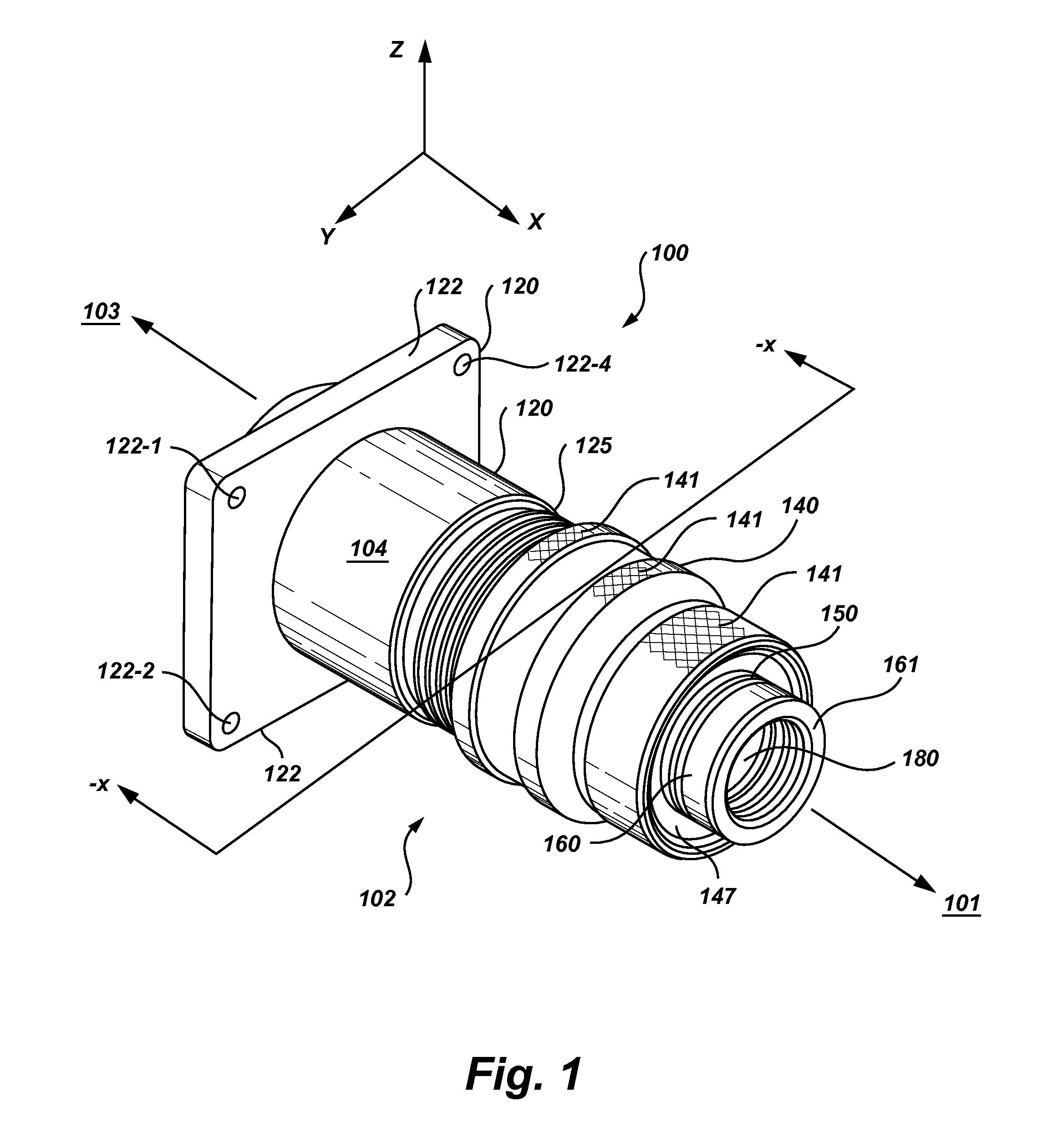
[0037]FIG. 1 shows a back perspective view of a connector in accordance with an embodiment of the present invention. The stationary housing 120 forms the front half of the connector, where the front end 103 connects to a female connector. An internal plu...


PUM


Abstract

An anchored 522 male electrical connector is provided. A stationary housing 520 is combined with a coupling ring 540 to form an outer housing. An internal plunger 560 is housed in and spans the length of the outer housing. The stationary housing 520 mounts onto an anchoring surface via an anchor mount 522, while the coupling ring 540 is free to rotate about the internal plunger 560. The coupling ring is rotated via a hand grasp 441. The coupling ring rotation 442, 443 translates into forward and aft movement of the pin assembly 515. The connector provides forward 520-1 and backward stops 520-4 for limiting pin insertion and extraction moves to desired distances. Rotation via triple start threads 548, 525 readily overcomes insertion and extraction resistance of a bulky multi-pin assembly 515 and provides a smooth and controlled electrical connection. The connector may be sized to meet multi-pin connector needs or military standards.

Description

BACKGROUND OF THE INVENTION[0001]The present invention relates generally to electrical connectors and more particularly to a male multi-pin connector device and method of providing repeatable consistent connection with a female receptacle connector.[0002]Making electrical contact across multiple pins for continuity across industrial cables can be accomplished with a variety of conventional connectors to include military standard connectors such as a D38999 series connector. Within military applications and in industry environments there are a multitude of applications where fine control over multiple contact pin engagements into contact pin receptacles is desirable.[0003]Plug-type connectors connected to testing circuitry may be repeatedly connected and disconnected to test a given device periodically and / or to test a number of devices. For example, testing of missile launch circuitry may be desired at periodic intervals. Testing of other aircraft circuitry or a launch connector may...

Claims


Application Information

Patent Timeline
Patent Type & Authority Patents(United States)
IPC IPC(8): H01R13/62
CPCH01R13/622H01R24/28H01R43/26H01R2107/00
Inventor WALTERS, JAMES C.
Owner WILLIAMSRDM
Why Eureka
Try Eureka