Intervertebral implant devices and methods for insertion thereof

a technology of intervertebral implants and proximal vertebrae, which is applied in the field of intervertebral implant devices for implantation between adjacent vertebrae, can solve problems such as obstacles in securely engaging the spinous process, and achieve the effect of reducing the distraction distance of the spinous process

Inactive Publication Date: 2012-08-21
PIONEER SURGICAL TECH INC
View PDF3 Cites 82 Cited by
  • Summary
  • Abstract
  • Description
  • Claims
  • Application Information

AI Technical Summary

Benefits of technology

[0008]In accordance with one aspect of the invention, an implant apparatus is provided that is configured to minimize trauma during insertion between spinous processes and securely space the adjacent spinous processes after insertion. In this regard, inserting and securing the implant apparatus reduces any pre-insertion distraction of the adjacent spinous processes and provides and maintains the predetermined spinous processes spacing.
[0010]In accordance with another aspect of the invention, an implant device is provided that allows for a plate member to be shifted along a spacer member and into engagement with adjacent spinous processes. In this regard, shifting the entire plate member allows a higher proportion of a surface of the plate member to be engaged with the spinous processes.
[0013]There are several advantages of inserting an implant device in an insertion orientation and securing the device after the device has been shifted to the implanted orientation. The first advantage is a reduction in the distraction distance of the spinous processes which must be achieved prior to insertion. As a result, movement of the spinous processes and the ligaments around the insertion site is reduced and, with reference to the ligaments, the opening therethrough for receiving the implant device is not larger than necessary. In addition, by securing the implant device after the device has been pivoted to the implanted orientation, the implant device can be pivoted from the implanted orientation so that the device can be repositioned to accommodate the spinal geometries of the implantation site without having to remove or disarm any automatically engaging securing mechanisms.

Problems solved by technology

The configuration of the prior art implant devices, in particular pivoted connection of the “plates” for engaging a side of a spinous process, presented obstacles in securely engaging the spinous process.
While the “plates” may in fact engage a side of the spinous process, the actual engagement area is limited by the location of the pivoted connection, the actual “plate” area potentially available to engage a spinous process, and the size of the predetermined seat portion relative to the size of the spinous processes to be seated.

Method used


Image

  • Intervertebral implant devices and methods for insertion thereof
  • Intervertebral implant devices and methods for insertion thereof
  • Intervertebral implant devices and methods for insertion thereof

Examples


Embodiment Construction

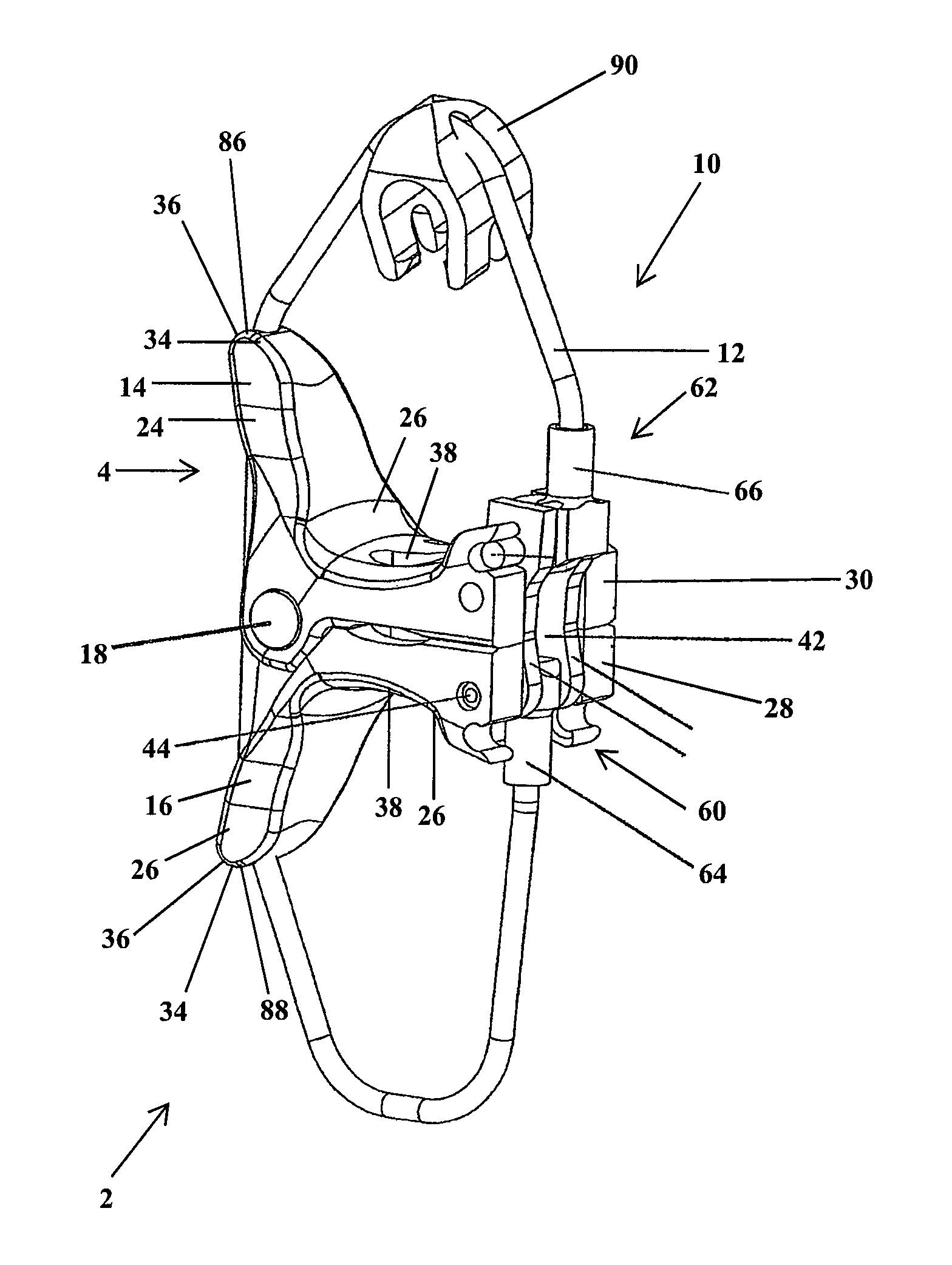
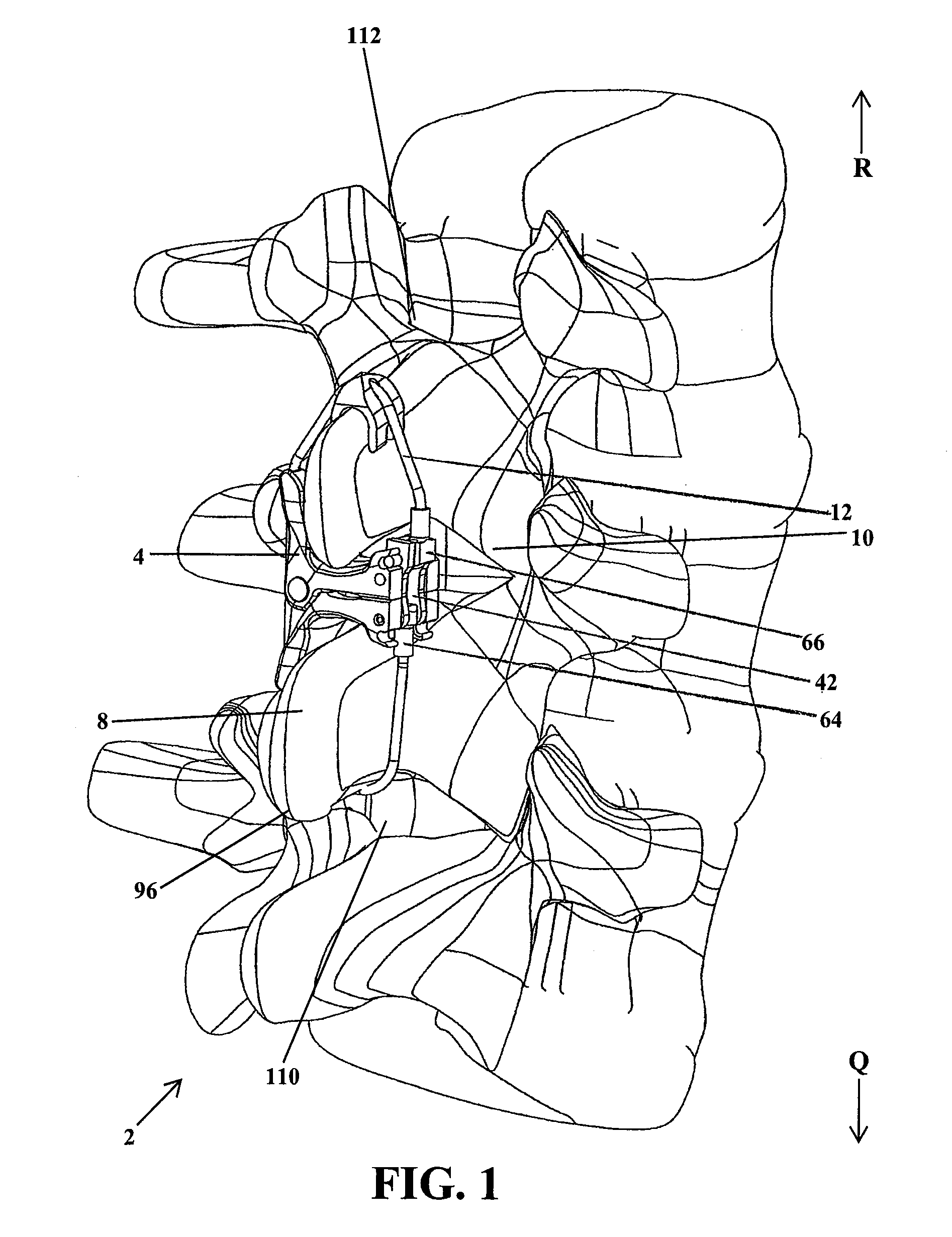
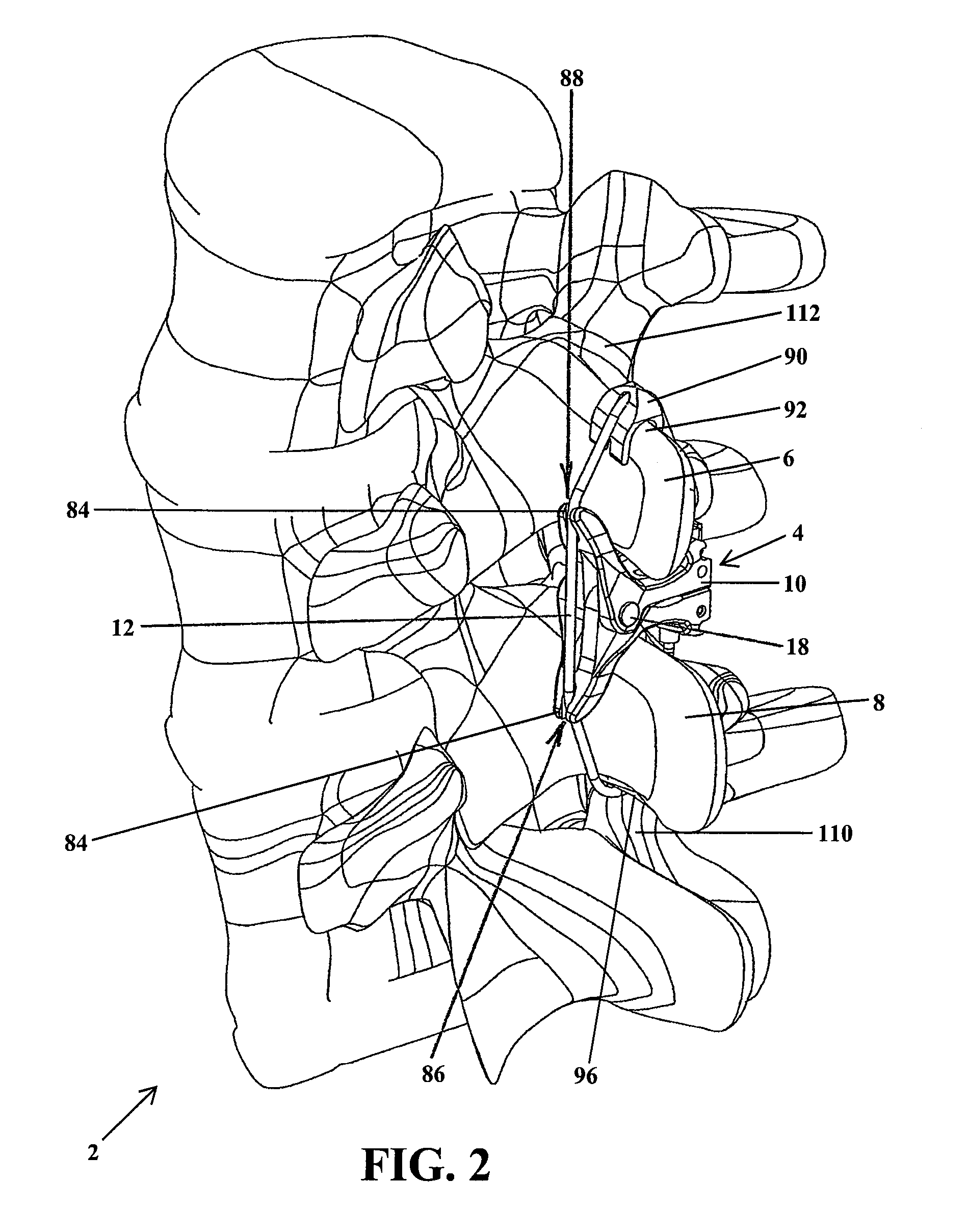
[0137]In FIG. 1, an implant apparatus 2 is shown having an interspinous spacing member 4 positioned between adjacent vertebral bodies 6 and 8 and secured or locked in place by a locking mechanism 10. The locking mechanism 10 is configured to secure engagement between the implant spacer 4 and the adjacent vertebral bone portions 6 and 8. As shown in FIG. 1 the locking mechanism 10 includes a flexible member 12 secured to and extending from the implant spacer 4, about the adjacent vertebral bone portions 6 and 8, and secured again to the implant spacer 4.

[0138]As shown in FIGS. 1-32, the interspinous spacing member includes an upper implant engaging member 14 for being positioned adjacent to and engaging an upper vertebral bone portion 6. Further, the spacing member 4 includes a lower implant engaging member 16 for being positioned adjacent to and engaging a lower vertebral bone portion 8. An exemplary interspinous spacing member 4 is disclosed in U.S. patent application Ser. No. 12 / 0...


PUM


Abstract

Implant apparatuses are provided for being inserted between adjacent vertebral bone portions and maintaining mechanical engagement with the vertebral bone portions. The implant apparatuses are generally constructed to be inserted in an insertion orientation and pivoted between the vertebral bone portions to an implanted orientation. The implant apparatuses are further secured in the implanted orientation to maintain engagement with the adjacent vertebral bone portions.

Description

CROSS REFERENCE TO RELATED APPLICATIONS[0001]This application is a non-provisional application claiming the benefit of U.S. Provisional Application No. 61 / 143,652 filed Jan. 9, 2009, and U.S. Provisional Application No. 61 / 155,102 filed Feb. 24, 2009, both of which are hereby incorporated in their entirety herein.FIELD OF THE INVENTION[0002]The invention relates to implant devices for implantation between adjacent vertebrae and, in particular, to implant devices positionable between spinous processes of adjacent vertebrae for both distracting and securing the adjacent vertebrae, and to methods for the implantation of such devices.BACKGROUND OF THE INVENTION[0003]A person may experience pain or limited mobility as a result of a variety of spinal conditions including trauma, deformity, disease, or other degenerative conditions. Existing methods of treating these conditions include surgical decompression of the affected area of the spine. One such technique employs the use of an inters...

Claims


Application Information

Patent Timeline
Patent Type & Authority Patents(United States)
IPC IPC(8): A61B17/70
CPCA61B17/7053A61B17/7065A61B17/7068A61B2017/0256
Inventor JACKSON, MICHAEL R.PIETILA, RUSSELL M.BAO, QI-BINDEPAS, WADETRUDEAU, JEFFREY L.
Owner PIONEER SURGICAL TECH INC
Why Eureka
Try Eureka