Ventilation member

a technology of ventilation member and support body, which is applied in the direction of space heating, domestic heating, machines/engines, etc., can solve the problem of difficulty in producing a large number of support bodies

Active Publication Date: 2012-08-21
NITTO DENKO CORP
View PDF12 Cites 38 Cited by
  • Summary
  • Abstract
  • Description
  • Claims
  • Application Information

AI Technical Summary

Benefits of technology

[0009]With such a configuration, the through-hole prevents the overlap of the main portion and each of the hooks in the direction in which the leg portions are inserted. This makes it possible, when the support body is produced, to use dies that can be separated in the insertion direction of the leg portions, that is, a die for forming the support body from the front surface side of the main portion and a die for forming the support body from the back surface side thereof. As a result, a large number of support bodies can be produced at a time. Thus, according to the present invention, a ventilation member suitable for mass production can be obtained.

Problems solved by technology

In the injection molding using these axial die and slide dies, it is difficult to produce a large number of support bodies 12 at a time.

Method used


Image

  • Ventilation member
  • Ventilation member
  • Ventilation member

Examples


first embodiment

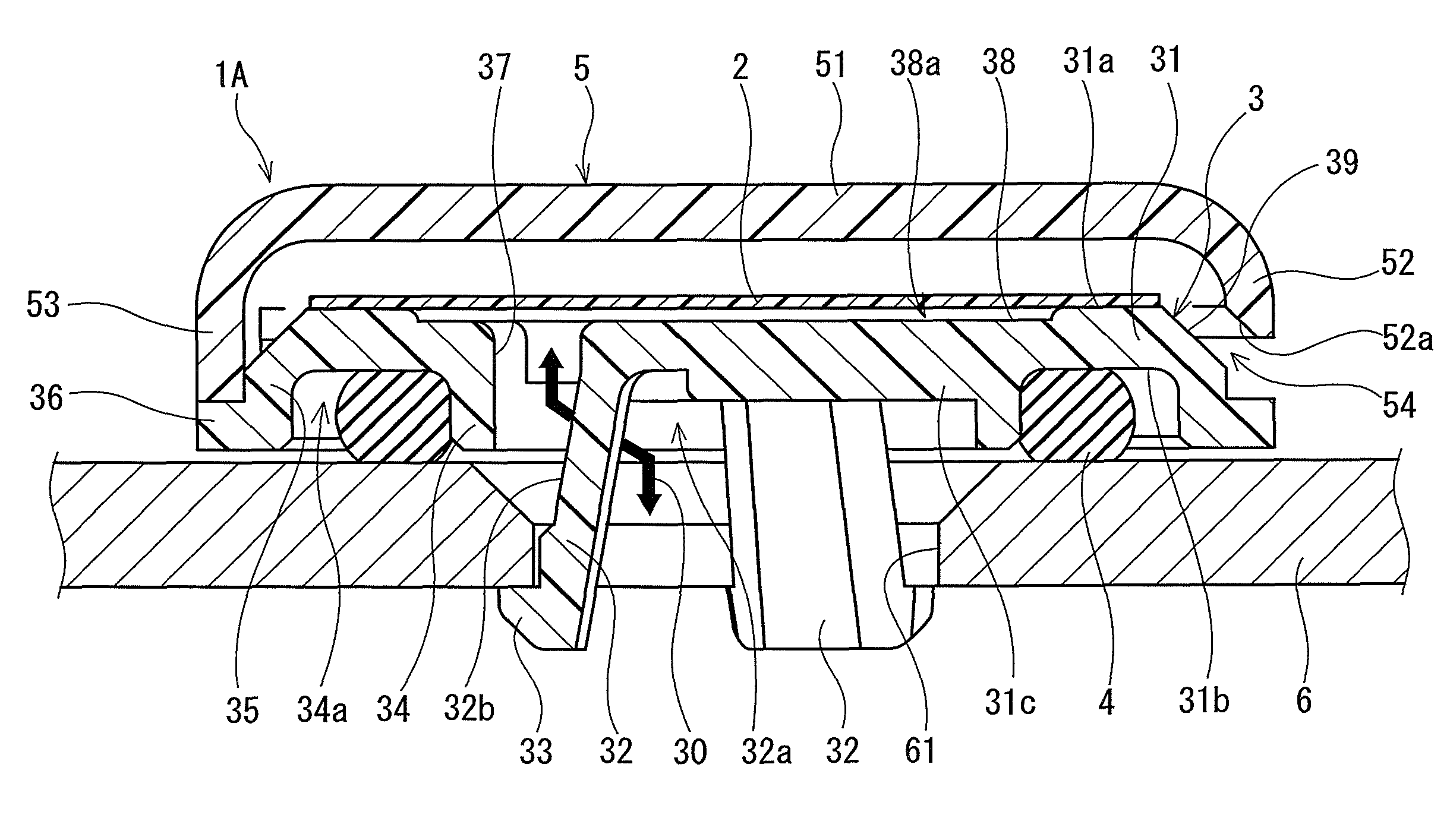
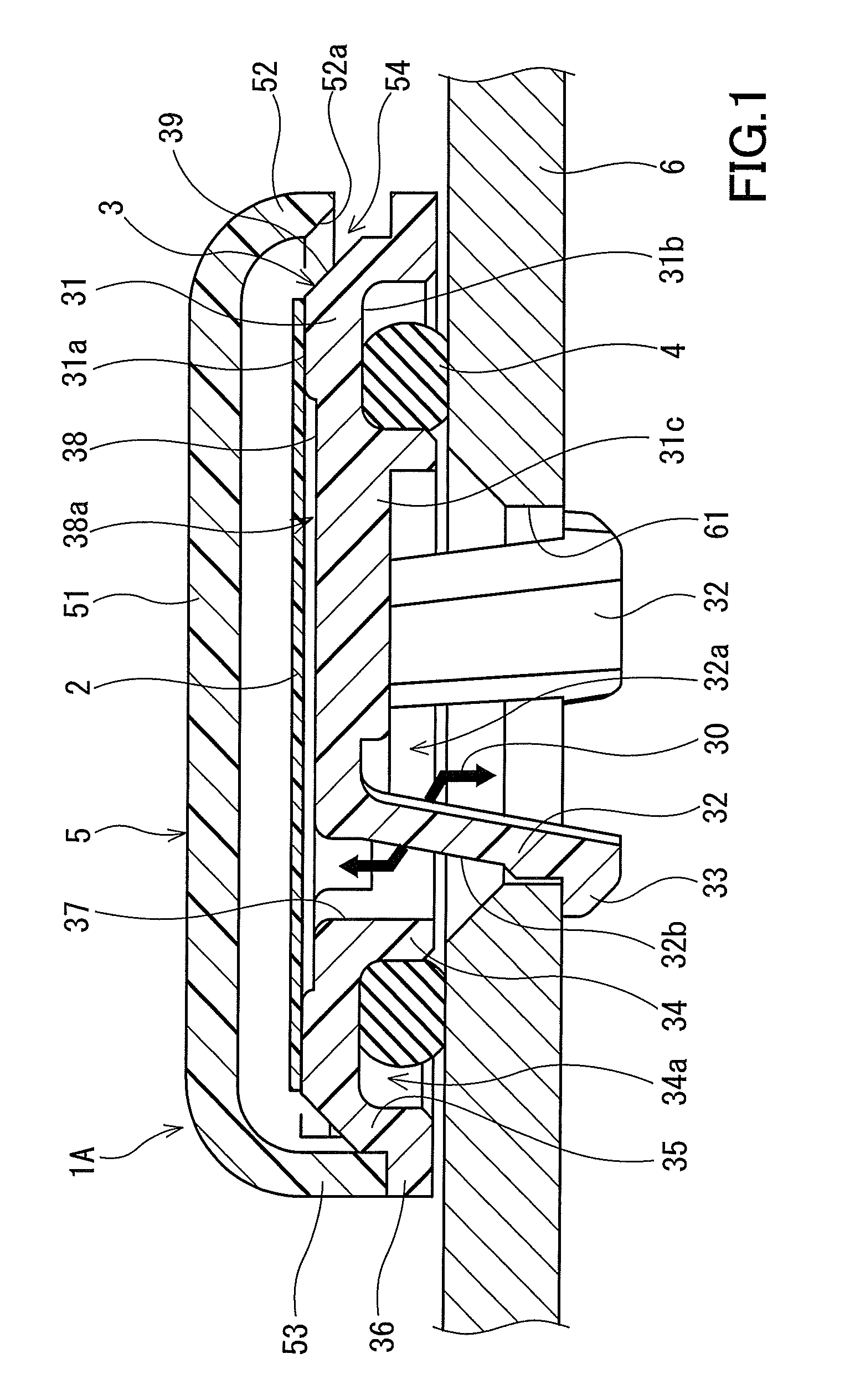
[0020]As shown in FIG. 1, a ventilation member 1A according to the first embodiment of the present invention is mounted in the position of a housing 6 where an opening 61 is formed. The ventilation member 1A includes a gas permeable membrane 2, a support body for supporting the gas permeable membrane 2, a sealing element 4 sandwiched between the support body 3 and the housing 6, and a cover body 5 for covering the gas permeable membrane 2 from the side opposite to the support body 3. The gas permeable membrane 2 has a function of blocking the entry of foreign substances such as water droplets and dust into the housing 6 while allowing gas to pass therethrough. The gas permeating action of the gas permeable membrane 2 maintains the pressures in and outside the housing 6 equal to each other. To simplify the description of the present embodiment, along the direction in which the support body 3 and the housing 6 sandwich the sealing element 4 therebetween, a direction toward the support...

second embodiment

[0050]Next, a ventilation member 1B according to a second embodiment of the present invention will be described with reference to FIG. 5. In the second embodiment, and the third and fourth embodiments to be described later, the same reference numerals are used to designate the same parts as in the first embodiment, and the description thereof is omitted except for the particular differences.

[0051]In the ventilation member 1B of the second embodiment, an elastic element that is formed integrally with the support body 3 to be filled in the accommodation groove 34a is used as the sealing element 4. The other configuration of the second embodiment is the same as that of the first embodiment.

[0052]In order to form such an elastic element, a pre-formed elastic material may be insert-molded in the support body 3, or two-color molding may be performed using the material of the elastic element and the material of the support body 3. When the sealing element 4 that is formed integrally with t...

third embodiment

[0053]As shown in FIG. 6 and FIG. 7, in a ventilation member 1C of the third embodiment, the projection height of the projecting portion 53 of the cover body 3 is reduced to increase the overlap between the side wall portion 52 and the support body 3. A plurality of grooves 51a extending radially from the center of the lower surface of the ceiling portion 51 to the side wall portion 52 are formed on the lower surface thereof. The other configuration of the third embodiment is the same as that of the first embodiment.

[0054]In this configuration, the distance between the ceiling portion 51a of the cover body 5 and the gas permeable membrane 2 is reduced, but the grooves 51a provide good ventilation. That is, according to the third embodiment, the thickness of the ventilation member 1C can be reduced further, with good ventilation.


PUM

PropertyMeasurementUnit
pore sizeaaaaaaaaaa
pore sizeaaaaaaaaaa
thicknessaaaaaaaaaa

Abstract

A ventilation member (1A) includes: a gas permeable membrane (2); a support body (3) for supporting the gas permeable membrane (2); and a sealing element (4). The support body (3) has: a main portion (31) having a front surface (31a) on which the gas permeable membrane (2) is attached and a back surface (31b) for pressing the sealing element (4) against a housing (6); and a plurality of leg portions (32) to be inserted into an opening (61) and each having a hook (33) at its end. The main portion (31) has, at positions corresponding to the hooks (33) in the direction in which the leg portions (32) are inserted, through-holes (37) through which the hooks (33) are exposed as seen from the side of the front surface (31a) of the main portion (31).

Description

[0001]This Application has priority to JP 2008-098418 and PCT / JP2009 / 052507.TECHNICAL FIELD[0002]The present invention relates to a ventilation member to be mounted to a housing.BACKGROUND ART[0003]Conventionally, in automotive electrical components such as lamps and ECUs (Electrical Control Units) for automobiles, OA (Office Automation) equipment, home appliances, medical devices, etc., an opening is formed in a housing for accommodating electronic parts, a control board, etc. to reduce the pressure fluctuation in the housing or to ventilate the housing, and a ventilation member is mounted in the position where the opening is formed. This ventilation member not only ensures ventilation between the inside and outside of the housing but also prevents foreign substances from entering the housing.[0004]For example, JP 2007-141629 A discloses a ventilation member as shown in FIG. 9. This ventilation member includes: a support body 12 for closing an opening 14a of a housing 14 with a gas...

Claims


Application Information

Patent Timeline
Patent Type & Authority Patents(United States)
IPC IPC(8): B01D53/22
CPCB60R16/0239F21S48/335H05K5/0213F21V31/03H02K5/10H02K2205/09F21S45/30H05K5/0216B60Y2410/10
Inventor YANO, YOUZOU
Owner NITTO DENKO CORP
Why Eureka
Try Eureka