Drug, drug guidance system, magnetic detection system, and drug design method

a drug guidance system and drug technology, applied in the direction of drugs, drug compositions, microcapsules, etc., can solve the problems of difficult practical application and achieve the effect of convenient application

Active Publication Date: 2012-08-21
IHI CORP +1
View PDF9 Cites 12 Cited by
  • Summary
  • Abstract
  • Description
  • Claims
  • Application Information

AI Technical Summary

Benefits of technology

[0021]According to the present invention, since drugs themselves will be magnetic, it is possible to guide the drugs to the target sites in the body by use of magnetism of the drugs themselves without using supports made from magnetic bodies as in the conventional cases. As a result, conventional problems such as difficulties in oral administration, the large size of carrier molecules in general, or technical problems in bond strength and affinity with the drug molecules can be resolved. Furthermore, it is possible to realize a drug delivery system which is easy to put into practical application.

Problems solved by technology

However, when the supports, which are magnetic bodies, are used as carriers as described above, difficulties in oral administration, the large size of carrier molecules in general, or technical problems in bond strength and affinity with the drug molecules have been pointed out and thus, practical application has been difficult.

Method used


Image

  • Drug, drug guidance system, magnetic detection system, and drug design method
  • Drug, drug guidance system, magnetic detection system, and drug design method
  • Drug, drug guidance system, magnetic detection system, and drug design method

Examples


first embodiment

[0047]Firstly, the first embodiment is described using an organic compound, more specifically, forskolin, as a drug candidate agent.

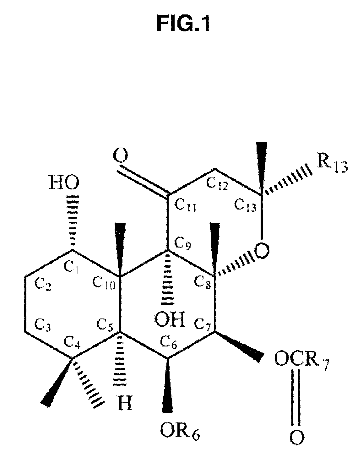
[0048]FIG. 1 is a diagram showing a basic molecular structural model of forskolin. In this drawing, R6, R7, and R13 show positions bonded with an atom or a molecule for modifying a side chain of forskolin. Depending on the type of atom or molecule bonded to these positions, the physical property of forskolin varies. In this drawing, one having H bonded to R6, CH3 bonded to R7, and CH═CH2 bonded to R13 is naturally occurring forskolin, and one having the side chain structure changed artificially, that is, forskolin produced by changing the atom or molecule for modifying R6, R7, and R13, is called a forskolin derivative. In FIG. 1, C1 to C13 represent a carbon atom (C).

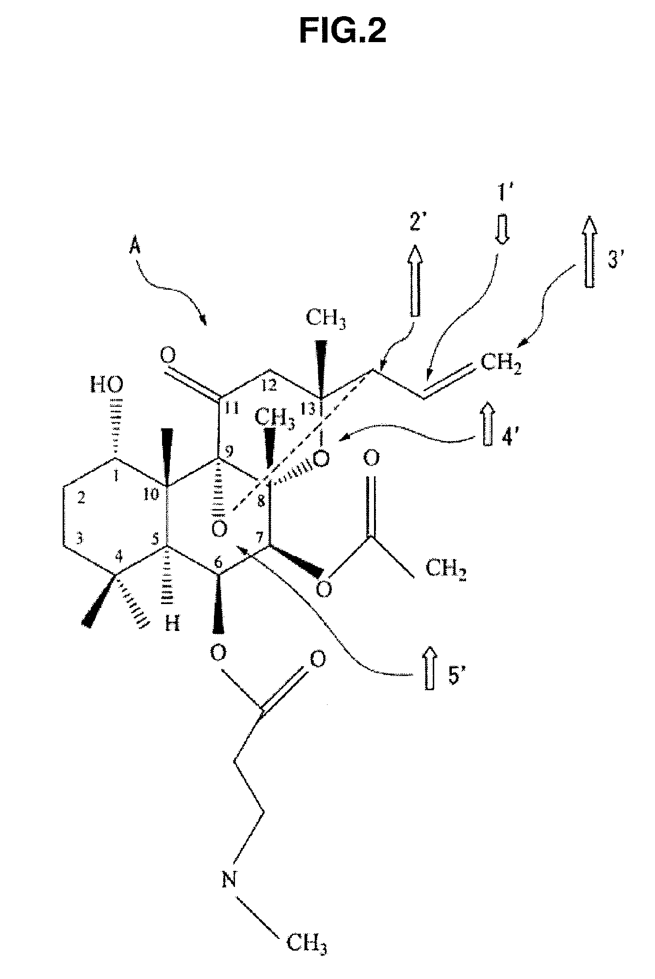
[0049]FIG. 2 is a diagram showing a basic molecular structural model of a magnetic (ferrimagnetic) forskolin derivative A. As shown in this drawing, the forskolin derivative A is one where ...

second embodiment

[0081]Next, a second embodiment is described using an inorganic compound, more specifically, cisplatin as an anticancer agent. Cisplatin is a metal complex (platinum complex) and classified as a platinum preparation among the anticancer agents.

[0082]FIG. 9 is a diagram of a basic molecular structural model of cisplatin with a standard composition. Using the computer simulation by the drug design method described in the first embodiment, this cisplatin with a standard composition is confirmed to be non-magnetic. On the other hand, FIG. 10A is a diagram of a basic molecular structural model of a cisplatin derivative (Cis-Pt-a3), which is derived by subjecting the cisplatin with a standard composition to side chain modifications. Additionally, FIG. 10B shows a three-dimensional molecular structure and spin-charge density distribution of the cisplatin derivative (Cis-Pt-a3) obtained by the abovementioned computer simulation.

[0083]In FIG. 10B, the regions 30 to 32 show upward spin-charge...


PUM

PropertyMeasurementUnit
weightaaaaaaaaaa
concentrationaaaaaaaaaa
magnetic fieldaaaaaaaaaa

Abstract

It is intended to provide a drug delivery system which makes it possible to solve the existing technical problems and is easily usable in practice. A drug, which comprises an organic compound or an inorganic compound and has been magnetized by modifying a side chain and / or crosslinking side chains, is induced by a magnetic force into target tissues or an affected part.

Description

CROSS-REFERENCE TO RELATED APPLICATIONS[0001]The present application is a 35 U.S.C. §§371 national phase conversion of PCT / JP2007 / 063011, filed Jun. 28, 2007, which claims priority of Japanese Patent Application Nos. 2006-177971 and 2007-056624, filed Jun. 28, 2006 and Mar. 7, 2007, respectively. The PCT International Application was published in the Japanese language.FIELD OF THE INVENTION[0002]The present invention relates to a drug, a drug guidance system, a magnetic detection system, and a drug design method.BACKGROUND[0003]Generally, drugs administered to the living body reach target sites and cause therapeutic effects by exerting pharmacological effects at the localized target sites. However, there will not be a cure if drugs reach tissues other than the target sites (that is, normal tissues). Consequently, how to guide drugs to the target sites efficiently is important in terms of therapeutic strategy. Such a technology for guiding drugs to the target sites is called drug del...

Claims


Application Information

Patent Timeline
Patent Type & Authority Patents(United States)
IPC IPC(8): A61F2/00A61K31/35C01G55/00A01N43/16A61K9/16A61K9/50A61K33/24A61K33/243
CPCA61K31/282A61K31/352A61K31/519A61K31/555G06F19/701A61K41/00A61K47/48023C07D493/08G01R33/5601A61K33/24A61K47/54G16C20/50G16C10/00A61P15/10A61P35/00A61K33/243
Inventor EGUCHI, HARUKIISHIKAWA
Owner IHI CORP
Why Eureka
Try Eureka