Tire sensor module and method for its manufacture

a technology of sensor module and assembly method, which is applied in the direction of protective material radiating elements, instruments, and ways, can solve the problems of complex mounting steps, and achieve the effect of simple and cost-effective manufacturing method, simplified mounting of circuit carriers in housings, and flexible adaptation

Active Publication Date: 2012-08-21
ROBERT BOSCH GMBH
View PDF19 Cites 11 Cited by
  • Summary
  • Abstract
  • Description
  • Claims
  • Application Information

AI Technical Summary

Benefits of technology

[0009]A manufacturing method of this type has the essential advantage that the geometry of the antenna may be adapted flexibly to the various applications. In the laser direct structuring method, a writing exposure method is used, so that only the data set, e.g., a CAD / CAM data set of the laser controller, is to be altered for different variants.
[0010]According to a second alternative specific embodiment thereto, the antenna may be laid as a metallic inlay part in the injection molding die and then extrusion coated by the housing plastic. This results in a simple and cost-effective manufacturing method.
[0011]The circuit carrier may be in contact with the antenna using a conductive adhesive bond between the circuit carrier and housing, the gluing allowing secure accommodation of the circuit carrier in the housing. Instead of the conductive adhesive bonds, pressure contacts, clamp connections, or press-in connections are also possible, so that no gluing is required during the final mounting of the circuit board in the housing. Furthermore, a contactless, in particular an inductive or capacitive connection of the antenna to the circuit carrier is also possible, so that no complex electrical contacting is required between the circuit carrier and the sensor housing. The mounting of the circuit carrier in the housing is thus significantly simplified.

Problems solved by technology

During the mounting of the sensor module in the tire by being vulcanized in, for example, the antenna is therefore to be oriented in accordance with its design, which correspondingly results in complex mounting steps.

Method used


Image

  • Tire sensor module and method for its manufacture
  • Tire sensor module and method for its manufacture
  • Tire sensor module and method for its manufacture

Examples


Embodiment Construction

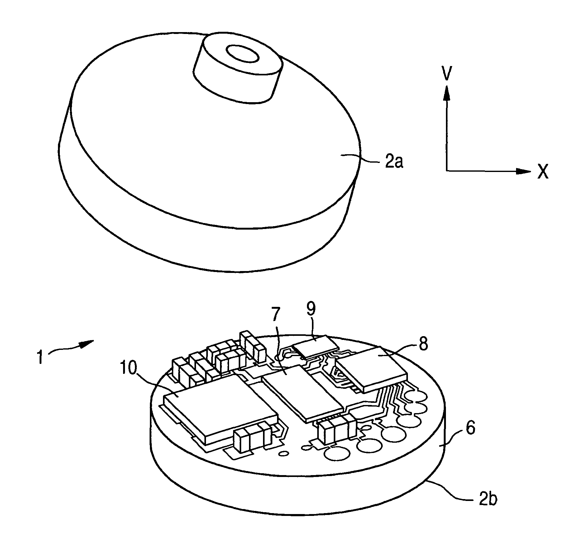
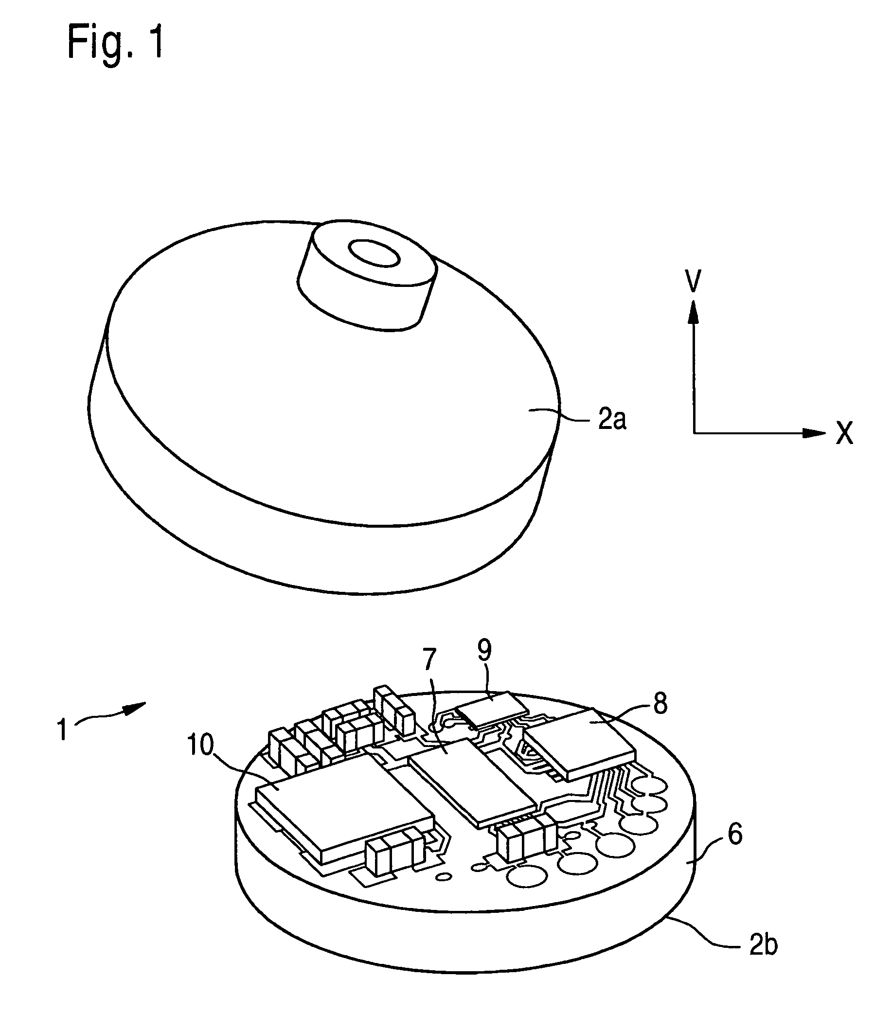
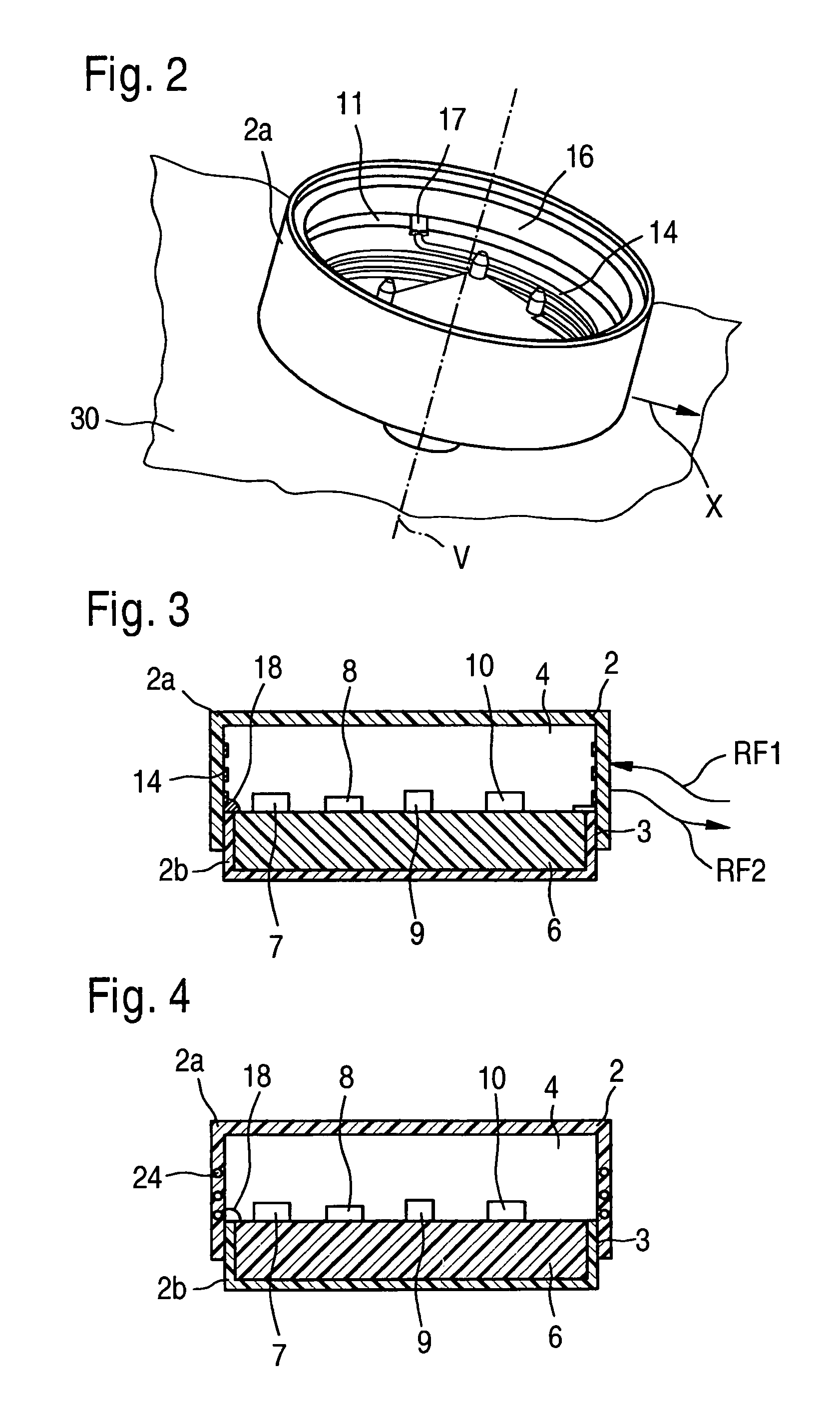
[0019]A tire sensor module 1 according to the present invention has a housing 2 having an upper housing part 2a and a lower housing part 2b, which are bonded to one another in a weld bond 3 and define a housing chamber 4 between them. Housing 2 is not designed to be hermetically sealed, at least for pressure measurements.

[0020]A circuit carrier 6, e.g., a circuit board 6 or also a ceramic substrate, on which a sensor element 7 (sensor IC) and further components are attached, e.g., an analysis and control ASIC 8 for recording the measured values of sensor element 7, possibly also for analyzing these measured signals, an RF ASIC 9, and an oscillator 10, is accommodated in housing chamber 4. Circuit carrier 6 may be placed on a shoulder 11 of housing part 2a, for example.

[0021]Sensor element 7 may be used for measuring different measured variables, in particular for measuring the tire pressure, as well as for measuring the internal temperature in the tire or accelerations and / or vibrat...


PUM

PropertyMeasurementUnit
pressureaaaaaaaaaa
temperatureaaaaaaaaaa
accelerationaaaaaaaaaa

Abstract

A tire sensor module having a circuit carrier, on or in which at least one sensor element is attached for measuring a measured variable, an antenna for transmitting sensor signals to a receiving unit of the vehicle, and a housing, in whose housing inner chamber the circuit carrier is received, the antenna being provided in the housing material of the housing or on a housing side of the housing.

Description

FIELD OF THE INVENTION[0001]The field of the invention relates to a tire sensor module.BACKGROUND INFORMATION[0002]Tire sensors are used in particular for measuring the tire pressure, i.e., as so-called tire pressure monitoring systems (TPMS). They are typically attached as sensor modules to the rim or the valve of the tire and transmit their data wirelessly with the aid of an antenna to a receiving unit of the vehicle, which relays the data to a central control unit of the vehicle.[0003]The antenna is generally provided as a wire outside the sensor. During the mounting of the sensor module in the tire by being vulcanized in, for example, the antenna is therefore to be oriented in accordance with its design, which correspondingly results in complex mounting steps.SUMMARY OF THE INVENTION[0004]According to the exemplary embodiments and / or the exemplary methods of the present invention, the antenna of the tire sensor module is provided in or on the housing of the tire sensor module, i...

Claims


Application Information

Patent Timeline
Patent Type & Authority Patents(United States)
IPC IPC(8): B60C23/00
CPCB60C23/0493H01Q1/2241B60C23/0452H01Q1/40Y10T29/49018
Inventor BUCK, THOMASPANNEK, THORSTENSCHOLZ, ULRIKEMUCHOW, JOERGKLETT, GUSTAVKNIES, SONJA
Owner ROBERT BOSCH GMBH
Why Eureka
Try Eureka