Systems and methods for optical receiver decision threshold optimization

a threshold optimization and optical receiver technology, applied in the field of optical receivers, can solve the problems of limiting and affecting the performance of pluggable optical transceivers. achieve the effect of optimizing improving the performance of the receiver

Active Publication Date: 2012-08-21
LUMENTUM OPERATIONS LLC
View PDF10 Cites 14 Cited by
  • Summary
  • Abstract
  • Description
  • Claims
  • Application Information

AI Technical Summary

Benefits of technology

[0008]In various exemplary embodiments, the present invention provides systems and methods for a receiver threshold optimization loop to provide self-contained automatic adjustment in a compact module, such as a pluggable optical transceiver. The receiver threshold optimization loop utilizes a performance metric associated with the receiver, such as FEC, to optimize performance of the receiver. The receiver is optimized through a change in the receiver threshold responsive to the performance metric. Advantageously, the present invention provides improved receiver performance through a continuous adjustment that is self-contained within the receiver, such as within a pluggable optical transceiver. The receiver threshold optimization loop can include a fine and a coarse sweep of adjustment from an initial setting.

Problems solved by technology

Accordingly, the receiver may experience errors based on these effects.
Advantageously, this enables interoperability among equipment vendors of pluggable transceivers, i.e. any MSA-compatible pluggable transceiver can be used in any host system designed to the MSA specification; however, these tightly defined characteristics limit the performance of pluggable transceivers since the MSA specifications were designed to maximize density and minimize cost, and not to provide advanced optical performance.
Disadvantageously, conventional pluggable optical transceivers do not provide advanced optical layer operations, administration, maintenance, and provisioning (OAM&P) and forward error correction (FEC).
However, such techniques are complex and often require external communication from the receiver, such as to receive the plurality of parameters and calculations.

Method used


Image

  • Systems and methods for optical receiver decision threshold optimization
  • Systems and methods for optical receiver decision threshold optimization
  • Systems and methods for optical receiver decision threshold optimization

Examples


Embodiment Construction

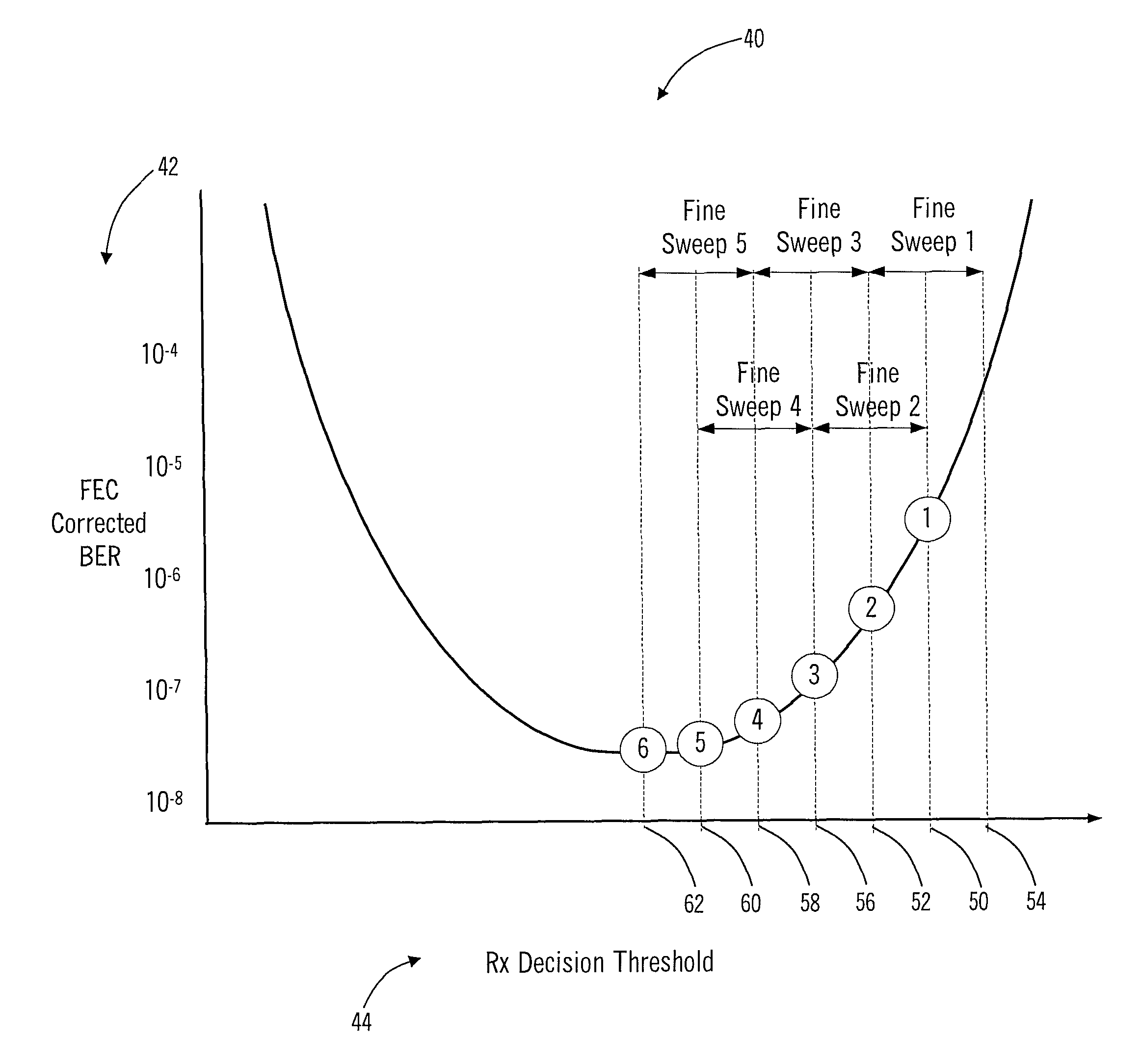
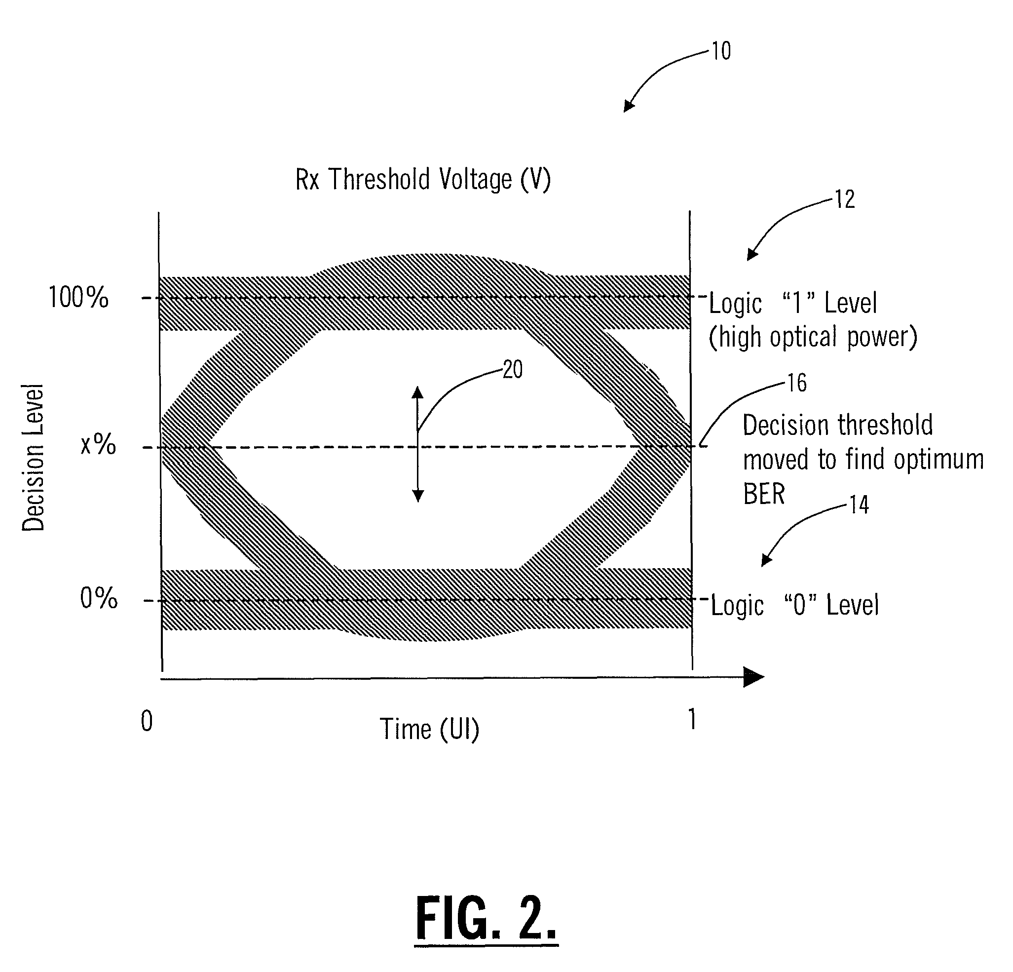
[0024]In various exemplary embodiments, the present invention provides systems and methods for a receiver threshold optimization loop to provide self-contained automatic adjustment in a compact module, such as a pluggable optical transceiver. The receiver threshold optimization loop utilizes a performance metric associated with the receiver, such as FEC, to optimize performance of the receiver. The receiver is optimized through a change in the receiver threshold responsive to the performance metric. Advantageously, the present invention provides improved receiver performance through a continuous adjustment that is self-contained within the receiver, such as within a pluggable optical transceiver. The receiver threshold optimization loop can include a fine and a coarse sweep of adjustment from an initial setting.

[0025]In an exemplary application, the receiver threshold optimization loop can operate within an MSA-compliant pluggable optical transceiver. Additionally, the pluggable opt...


PUM


Abstract

The present invention provides systems and methods for a receiver threshold optimization loop to provide self-contained automatic adjustment in a compact module, such as a pluggable optical transceiver. The receiver threshold optimization loop utilizes a performance metric associated with the receiver, such as FEC, to optimize performance of the receiver. The receiver is optimized through a change in the receiver threshold responsive to the performance metric. Advantageously, the present invention provides improved receiver performance through a continuous adjustment that is self-contained within the receiver, such as within a pluggable optical transceiver compliant to a multi-source agreement (MSA). The receiver threshold optimization loop can include a fine and a coarse sweep of adjustment from an initial setting.

Description

FIELD OF THE INVENTION[0001]The present invention relates generally to optical receivers. More particularly, the present invention provides systems and methods for a receiver threshold optimization loop to provide self-contained automatic adjustment in a compact module, such as a pluggable optical transceiver defined by a Multi-Source Agreement (MSA).BACKGROUND OF THE INVENTION[0002]Optical receivers are configured to receive optical signals which include modulated information streams, and to provide an electrical signal corresponding to the modulated information streams. The corresponding electrical signal can include threshold voltages which determine the value of the information, e.g. a logical “1” and “0” bit. Note, the information can be modulated in a variety of formats, such as on-off keying, multi-level coding, phase modulation, etc. Referring to FIG. 1, an eye diagram 10 illustrates a conventional mechanism for receiver threshold voltage determination of a receiver. Eye dia...

Claims


Application Information

Patent Timeline
Patent Type & Authority Patents(United States)
IPC IPC(8): H04L25/06H03D1/04
CPCH04B10/695
Inventor CAI, QINGZHONGSUN, XIAOGUANGCARDONA, GABRIEL E.
Owner LUMENTUM OPERATIONS LLC
Why Eureka
Try Eureka