This helps you quickly interpret patents by identifying the three key elements:
Problems solved by technology
Method used
Benefits of technology
Benefits of technology
[0012]The present invention discloses, in certain aspects, a handling system for installing a rig structure on a drilling rig, the handling system including movement apparatus for initially supporting a rig structure and for moving on ground adjacent a drilling rig to position the rig structure with respect to the drilling rig, the drilling rig having a substructure with a drill floor; support apparatus movably connected to the drill floor for selectively supporting the rig structure, the support apparatus movable out of the way to facilitate positioning of the rig structure with respect to the drill floor and the support apparatus movable adjacent the rig structure for connection thereto; and raising apparatus connected to the support apparatus, the raising apparatus for selectively raising the rig structure with respect to the drill floor.
Problems solved by technology
Various problems and disadvantages are associated with installing structure, e.g. a doghouse, on a rig using a crane.
Method used
Image
Click on the blue label to locate the original text in one second.
Reading with bidirectional positioning of images and text.
Examples
Embodiment Construction
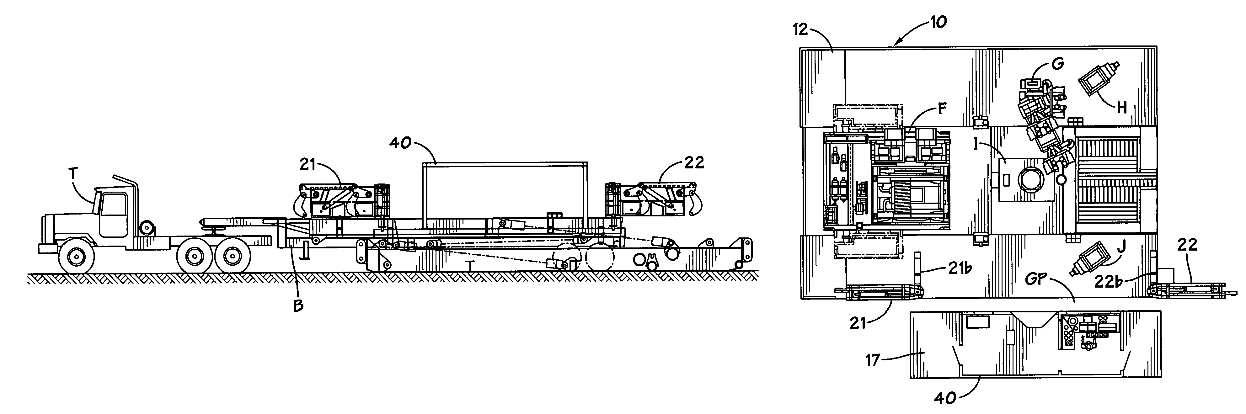
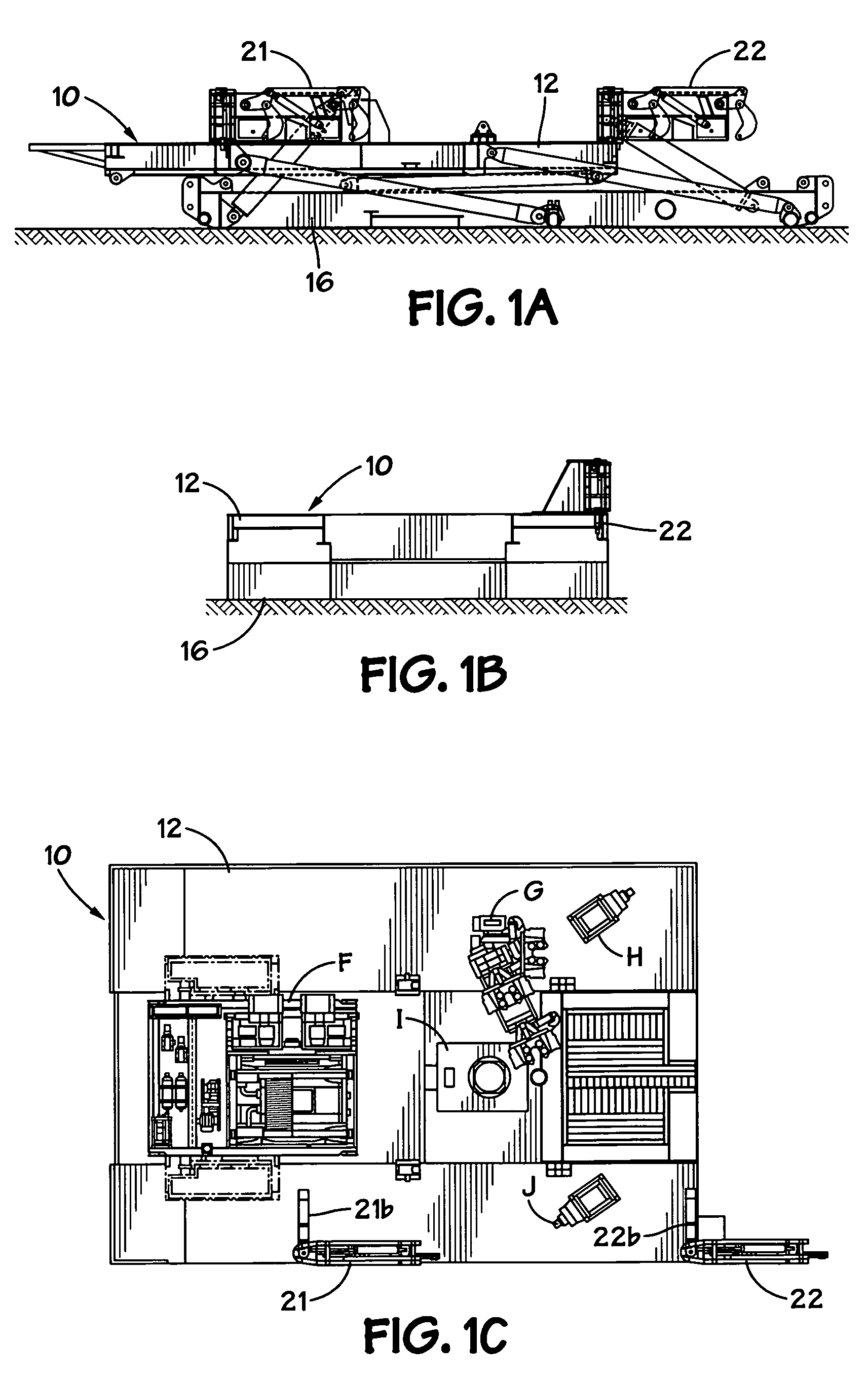
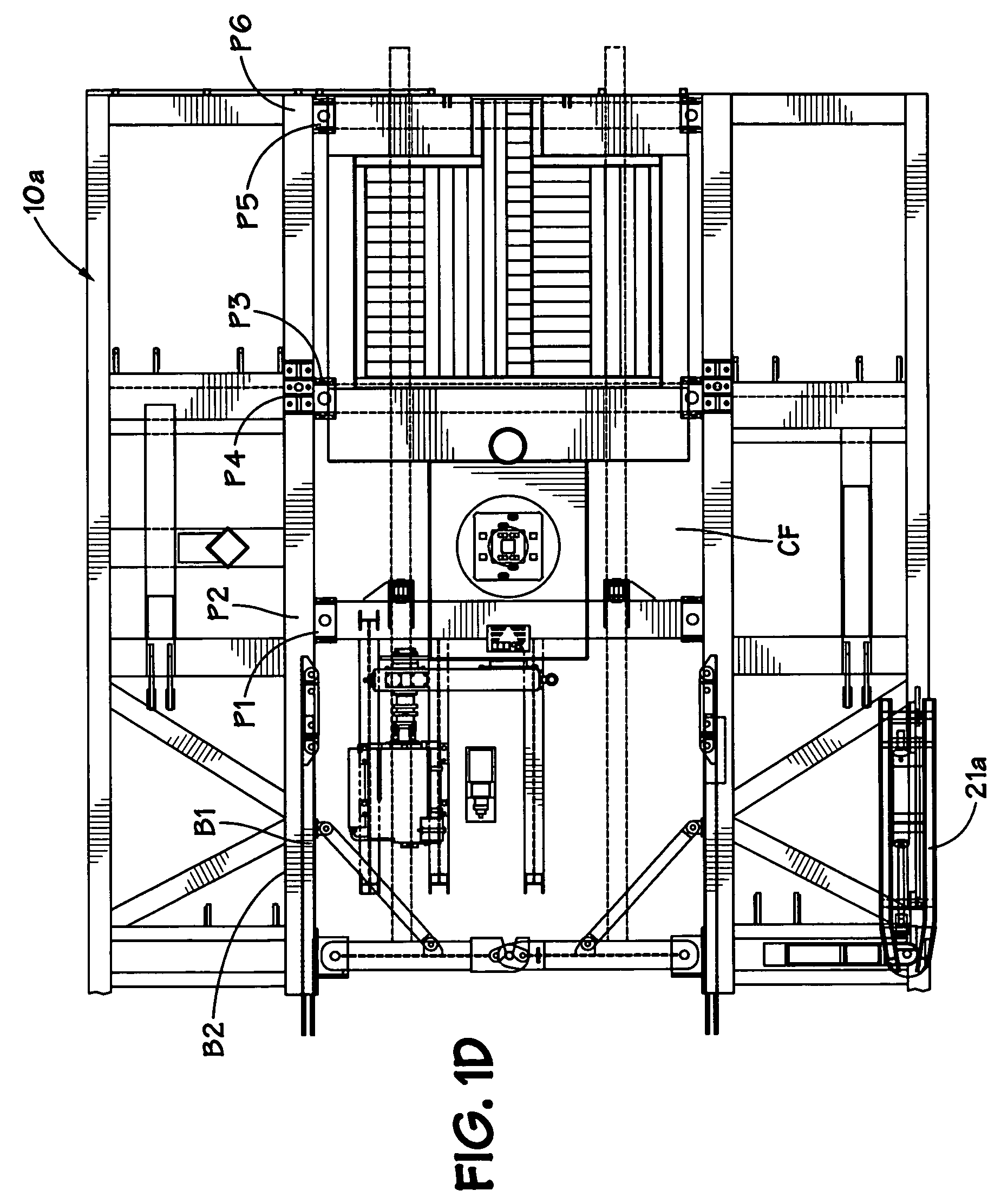
[0079]FIGS. 1A, 1B and 1C show a rig 10 with rig equipment F, G, H, I, J on a drill floor 12, the drill floor 12 is raised by a substructure 16 to which the drill floor 12 is connected. Connected to the substructure 16 is a structure lifting and movement apparatus which includes a left suspending arm 21 and a right suspending arm 22.
[0080]Each suspending arm 21, 22 (see FIGS. 2A, 2B) has support beams (see beams 21l, 21m, FIG. 2B) and is pivotably connected with pins (e.g. see pins 21c, 21d for the arm 21) to a base 21b, 22b, respectively, and these bases are secured or formed integrally of the drill floor 12. The suspending arms 21, 22 can pivot 180° on their bases. Each suspending arm has a linkage assembly raised and lowered by an hydraulic cylinder apparatus 23 (one arm at each end of the skid 17 of the structure 40). A piston 23p of each apparatus 23 movable in a housing 23h is connected to a first top link 24t. A pin 23zconnects a lower end of the housing 23h to the arm 21. A ...
PUM
Abstract
A method for installing rig structure (e.g. cabin, house, a doghouse) on a drilling rig, the method including: connecting support apparatus to a substructure of a drilling rig, supporting a drilling floor; moving a movement apparatus supporting a rig structure to position it adjacent the support apparatus, by moving movement apparatus on ground adjacent the substructure, moving the support apparatus into a connecting orientation with respect to the structure; connecting raising apparatus to the structure, the raising apparatus connected to the support apparatus; raising the structure up to the drill floor with the raising apparatus; and securing the structure to the support apparatus. This abstract is provided to comply with the rules requiring an abstract which will allow a searcher or other reader to quickly ascertain the subject matter of the technical disclosure and is submitted with the understanding that it will not be used to interpret or limit the scope or meaning of the claims, 37 C.F.R. 1.72(b).
Description
BACKGROUND OF THE INVENTION[0001]1. Field of the Invention[0002]This invention is directed to drilling rigs; drilling rigs with structure thereon such as a doghouse, driller's cabin, building, or electrical control house; and to methods for installing such structures on a rig.[0003]2. Description of Related Art[0004]The prior art discloses a variety of rigs used in drilling and various wellbore operations; for example, and not by way of limitation, U.S. Pat. Nos. 3,340,938; 3,807,109; 3,922,825; 3,942,593; 4,269,395; 4,290,495; 4,368,602; 4,489,526; 4,569,168; 4,837,992; 6,634,436; 6,523,319 and 7,306,055 and the references cited in these patents—all these patents incorporated fully herein for all purposes. The prior art discloses a variety of systems and methods for assembling and raising components of a drilling rig; for example, and not by way of limitation nor as an exhaustive listing, the disclosures in U.S. Pat. Nos. 2,993,570; 3,201,091; 3,262,237; 3,749,183; 4,221,088; 4,269...
Claims
Application Information
Patent Timeline
Application Date:The date an application was filed.
Publication Date:The date a patent or application was officially published.
First Publication Date:The earliest publication date of a patent with the same application number.
Issue Date:Publication date of the patent grant document.
PCT Entry Date:The Entry date of PCT National Phase.
Estimated Expiry Date:The statutory expiry date of a patent right according to the Patent Law, and it is the longest term of protection that the patent right can achieve without the termination of the patent right due to other reasons(Term extension factor has been taken into account ).
Invalid Date:Actual expiry date is based on effective date or publication date of legal transaction data of invalid patent.
Patent Type & AuthorityPatents(United States)
IPC IPC(8): B66C23/26B66C23/60B66C23/30
CPCE21B7/023E21B15/00
InventorDONNALLY, ROBERT BENJAMINREN, CHUNQIAOMCCURDY, STUART ARTHUR LYALLLIUI, XI LINSHENG, HUI CHUNYU, YANCHEN, HE HUI

