Exhalation port with built-in entrainment valve

a technology of entrainment valve and inhalation port, which is applied in the direction of respirator, functional valve type, transportation and packaging, etc., can solve the problems of patient re-breathing their own carbon dioxide, gas flow not being delivered to the patient interface, and complicated patient circuit and patient interface system

Active Publication Date: 2012-08-28
RIC INVESTMENTS LLC
View PDF39 Cites 58 Cited by
  • Summary
  • Abstract
  • Description
  • Claims
  • Application Information

AI Technical Summary

Benefits of technology

[0012]A valve structure is provided to prevent the valve element from completely blocking the exhaust gas flow when in the second position. This feature of the present invent

Problems solved by technology

Should the gas flow/pressure generating device become dysfunctional, for example as a result of a power outage or other problem, a flow of gas will no longer be delivered to the patient interface.
While the conventional exhaust port may provide some fresh gas to the patient, the amount of gas it can provide is typically not adequate

Method used


Image

  • Exhalation port with built-in entrainment valve
  • Exhalation port with built-in entrainment valve
  • Exhalation port with built-in entrainment valve

Examples


first embodiment

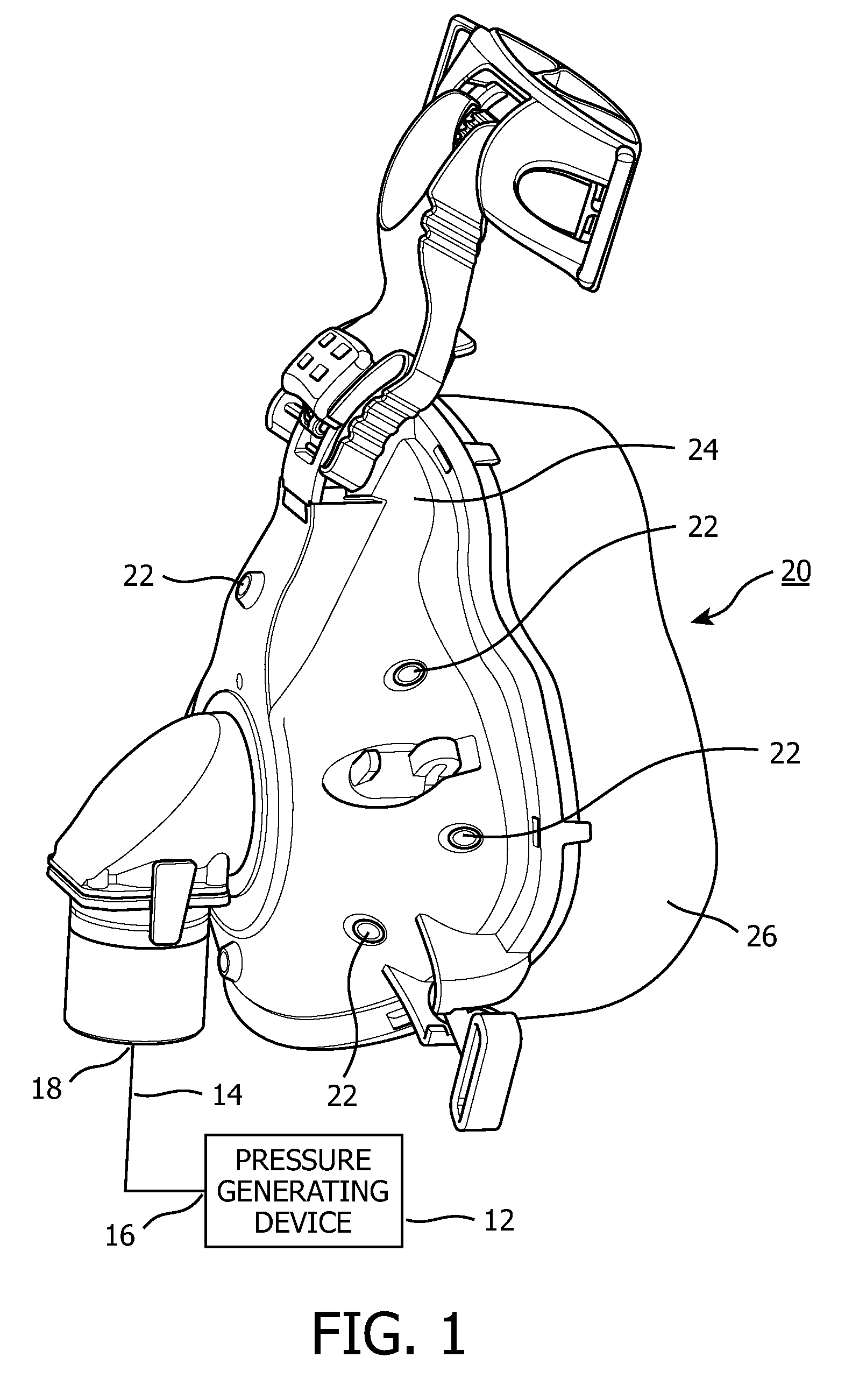
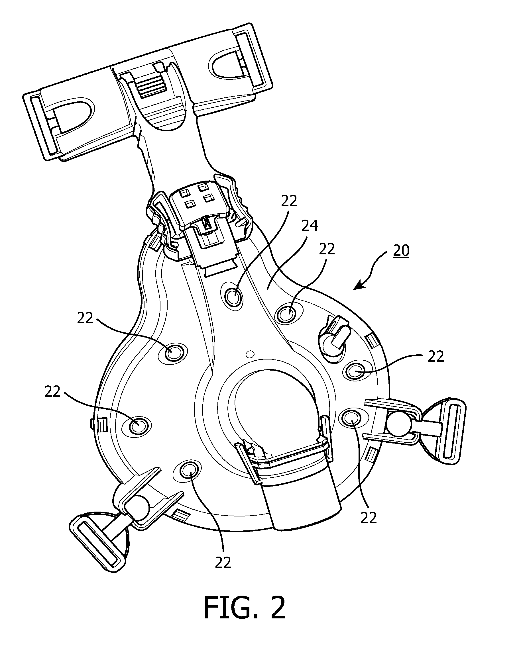
[0033]FIGS. 3-5 illustrate in greater detail valve device 22 according to the principles of the present invention. In this illustrated embodiment, valve device 22 is incorporated into patient interface 20. Specifically, valve device 22 is integral with faceplate 24. The position of valve device 22 on the patient interface illustrated in FIGS. 1-2 is just one example according to the present invention. It is to be understood that the valve device or devices could be located at other positions, such as on the patient circuit, the coupling between the patient circuit and the faceplate, the seal, or any combination thereof.

[0034]In this exemplary embodiment, valve device 22 comprises a frusta-conical shaped valve body 28 extending outwardly from the patient interface faceplate 24 (away from the patient in use). Valve body 28 further includes a frusta-conical shaped interior chamber 30 having an interior sidewall 31. Interior chamber 30 includes an inlet 32 at faceplate 24 and an outlet ...

third embodiment

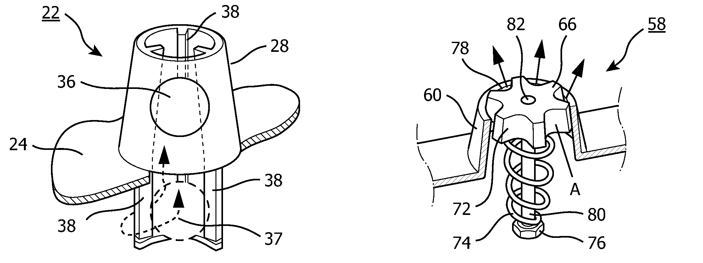
[0041]a valve device 49, which is also gravity based, is shown in FIG. 8. In this embodiment, the ribs are omitted from sidewall 50, so that the sidewalls of the interior chamber are smooth. The valve element is again a ball 52. However, ball 52 includes protrusions or bumps 54 to prevent the valve device from completely blocking the flow of exhaust gas through the valve body when the valve element is in the “closed” position. Bumps 54 comprise a valve structure preventing the ball from completely blocking the valve device from the atmosphere, while permitting a flow of exhaust gas through the valve device and the atmosphere. The present invention also contemplates that grooves 53 can be provided in the ball 52, in addition to, or in place of, the bumps 54, so that exhaust gas can flow around the ball 52 through the groove 53. The height of the bumps define the flow rate through the valve device when in the “closed” position. It should also be understood that the present invention c...

fourth embodiment

[0042]a valve device 58 according to the principles of the present invention is shown in FIGS. 9-10. In this embodiment, the biasing force acting on the valve element is a spring rather than gravity. In other words, the biasing that urges the valve element to return the “open” position is a spring force, rather than a gravitational force. In this embodiment, valve device 58 has a frusta-conical shaped valve body 60 that defines a chamber 62 having smooth interior sidewall 64. The valve element in this exemplary embodiment is a frusta-conical shaped plug 66 having a first side 68, a second side 70, and a plurality of radially spaced grooves 72 disposed about its perimeter. Grooves 72 extend from the first side to the second side. It should be noted that plug 66 could also be described has having a plurality of protrusions 73 disposed around it perimeter with a gap 72 between each protrusion. A spring 74 is attached to second side 70 of plug 66 and to a retaining member 76, which is a...


PUM


Abstract

A pressure sensitive valve device for use with respiratory equipment of the type that produces a pressurized flow of breathing gas. The valve device combines the exhalation and entrainment functions in one valve with a single air path. The valve device provides an exhaust valve function during normal operation and provides a less restricted access to the ambient atmosphere in the event of respiratory equipment malfunction. The valve device includes a valve element that moves between at least two positions. During normal operation, when the pressure generating system is generating a flow of gas, the valve element is in a “closed” or “exhaust valve” position. When in the exhaust valve position, the gas flow to the atmosphere is restricted without being completely blocked off. When the flow of gas is decreased or interrupted, the valve element moves to the “entrainment valve” or “open” position that allows a greater, i.e., less restricted flow, of gas between the user and the ambient atmosphere.

Description

CROSS-REFERENCE TO RELATED APPLICATIONS[0001]This application claims priority under 35 U.S.C. §119(e) from provisional U.S. patent application No. 60 / 638,678, filed Dec. 22, 2004, the contents of which are incorporated herein by reference.BACKGROUND OF THE INVENTION[0002]1. Field of the Invention[0003]The present invention relates to an apparatus adapted for use with respiratory equipment and, more particularly, to an exhalation port device with a built-in entrainment valve feature.[0004]2. Description of the Related Art[0005]Pressure support systems that provide a flow of gas to an airway of a patient at an elevated pressure via a patient circuit to treat a medical disorder are well known. For example, it is known to use positive airway pressure devices, such as a continuous positive airway pressure (CPAP) device, to supply a constant positive pressure to the airway of a patient to treat obstructive sleep apnea (OSA) as well as other disorders. It is also known to provide a positiv...

Claims


Application Information

Patent Timeline
IPC IPC(8): A61M16/06F16K17/00A62B18/10F16K15/00
CPCA61M16/06A61M16/0816A61M16/20A62B18/10A61M16/208A61M2205/0216A61M16/0638A61M16/0655Y10T137/7847Y10T137/7848
Inventor HO, PETER CHI FAIDIPASQUALE, JAMESDIACOPOULOS, ELIAS G.
Owner RIC INVESTMENTS LLC
Why Eureka
Try Eureka