Eureka AIR delivers breakthrough ideas for toughest innovation challenges, trusted by R&D personnel around the world.

Image blur correction unit, lens barrel device, and camera apparatus

a technology of image blur and correction unit, which is applied in the field of image blur correction unit, lens barrel device, and camera apparatus, can solve the problems of increased cost, increased frequency of capturing images, and difficulty in reducing the thickness of the lens barrel, so as to reduce the thickness and size

Active Publication Date: 2012-08-28
SONY CORP
View PDF18 Cites 0 Cited by
  • Summary
  • Abstract
  • Description
  • Claims
  • Application Information

AI Technical Summary

Benefits of technology

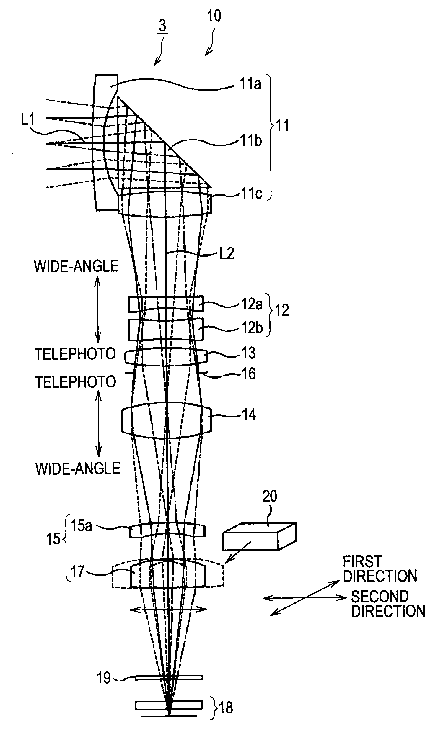
[0014]According to each of the embodiments of the present invention, since the one of the elements of the lens system or the imager is disposed outside the area surrounded by the first and second guide means when the first and second guide means are viewed from the optical axis, a lens barrel can be reduced in thickness and size.

Problems solved by technology

Accordingly, this leads to an increased frequency of capturing an image blurred due to camera shake upon shooting a subject.
This leads to an increased cost.
In an optical-axis bending lens system in which the optical axis is bent at an angle of 90 degrees, if a correction lens is disposed in an area surrounded by four shafts in a manner similar to Japanese Unexamined Patent Application Publication No. 3-188430, it is difficult to reduce the thickness of a lens barrel, namely, further reduce the thickness thereof in the direction along the optical axis.
Upon reducing the size or thickness of the camera, however, it is difficult to ensure that the opening is sufficiently larger than the optical effective aperture.
Disadvantageously, a stray light component may enter the optical path, thus causing a ghost image.

Method used


Image

  • Image blur correction unit, lens barrel device, and camera apparatus
  • Image blur correction unit, lens barrel device, and camera apparatus
  • Image blur correction unit, lens barrel device, and camera apparatus

Examples


Embodiment Construction

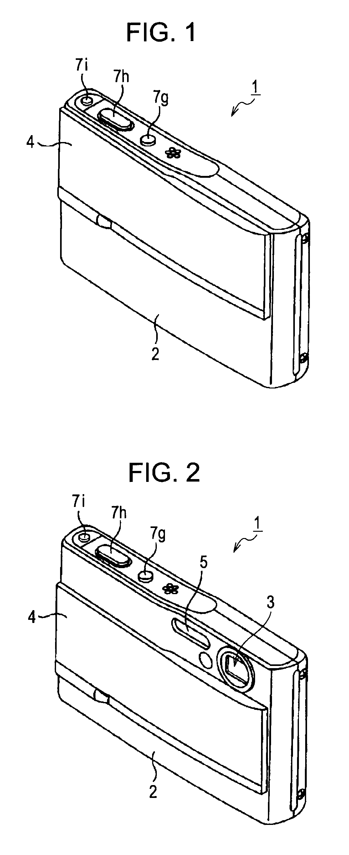
[0031]A digital still camera 1 according to an embodiment of the present invention will be described with reference to the drawings. The digital still camera 1 will be simply referred to as “camera 1” below.

(1) Appearance Configuration of Digital Still Camera

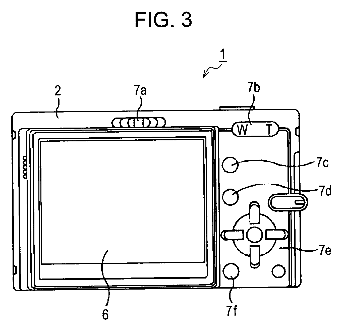
[0032]Referring to FIGS. 1 to 3, the camera 1 according to the present embodiment of the present invention uses a semiconductor recording medium as an information recording medium and converts an optical image, captured by shooting a subject, into an electrical signal through an imager (e.g., a charge-coupled device (CCD) imager or a complementary metal-oxide semiconductor (CMOS) imager) so that the optical image can be recorded in the semiconductor recording medium or be displayed on a display unit, such as a liquid crystal display.

[0033]The camera 1 has a laterally long and low-profile camera body 2. The camera body 2 has a lens 3 in the front thereof such that the lens 3 is disposed in one upper corner. The camera body 2 furt...


PUM


Abstract

An image blur correcting unit allows the optical axis of a lens system to coincide with the center of an imager, thus correcting an image blur. The unit includes a stationary member and a holder member. The holder member holds either one of the elements of the lens system or the imager and moves relative to the stationary member in a first direction and a second direction, the first and second directions being orthogonal to each other in a plane orthogonal to the optical axis. The unit further includes a first guide section and a second guide section for guiding the holder member in the first and second directions during movement, and a driving section moving the holder member in the first and second directions. The one of the elements of the lens system or the imager is disposed outside an area surrounded by the first and second guide sections.

Description

CROSS REFERENCES TO RELATED APPLICATIONS[0001]The present invention contains subject matter related to Japanese Patent Application JP 2008-055326 filed in the Japanese Patent Office on Mar. 5, 2008, the entire contents of which are incorporated herein by reference.BACKGROUND OF THE INVENTION[0002]1. Field of the Invention[0003]The present invention relates to an image blur correction unit, a lens barrel device, and a camera apparatus each correcting an image blur caused by a vibration upon shooting.[0004]2. Description of the Related Art[0005]Compact cameras are being requested to be further reduced in size and have higher power (magnification) and higher pixel resolution. Accordingly, this leads to an increased frequency of capturing an image blurred due to camera shake upon shooting a subject. As for a mechanism for shifting an optical element to compensate for camera shake, a retractable optical system and an optical-axis bending optical system each include a mechanism axially sl...

Claims


Application Information

Patent Timeline
Patent Type & Authority Patents(United States)
IPC IPC(8): H04N5/228
CPCG02B15/177G02B27/646
Inventor MAEDA, IPPEINAKAYAMA, TATSUYUKIOGIYAMA, HIROTOMUTOH, YOSHINORIMATSUBARA, YASUTO
Owner SONY CORP
Why Eureka
Eureka Blog
Learn More