
Plasma burner and diesel particulate filter trap

a technology of particulate filter and burner, which is applied in the direction of filtration separation, auxillary pretreatment, separation process, etc., can solve the problems of incomplete combustion of fuel, large amount of smoke generated, electric heater, etc., and achieve the effect of enlarger flame, and effectively oxidizing and removing pms

Active Publication Date: 2012-09-04
KOREA INST OF MACHINERY & MATERIALS
View PDF29 Cites 3 Cited by
  • Summary
  • Abstract
  • Description
  • Claims
  • Application Information

AI Technical Summary

Benefits of technology

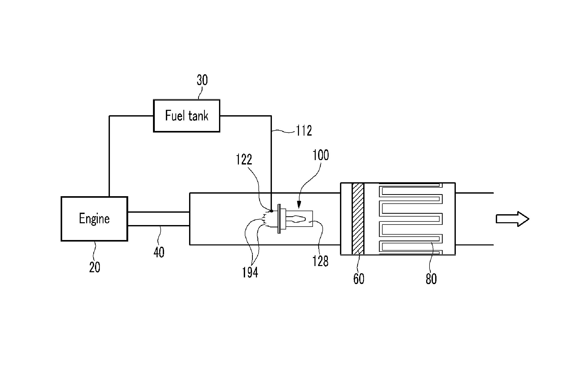
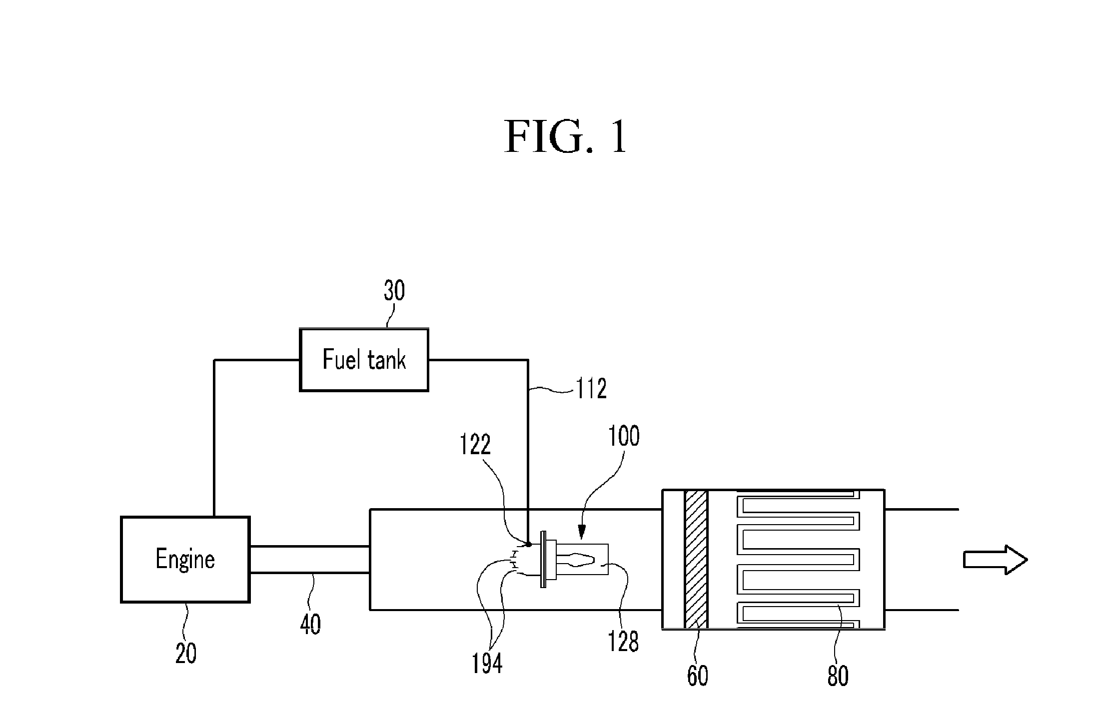
The present invention provides a plasma burner and a DPF that can effectively oxidize and remove PM from exhaust gas by preheating fuel and maximizing the use of space within the exhaust conduit. The plasma burner includes a fuel inflow conduit that connects to a fuel tank, a plasma burner that mixes and heats fuel and air, and a reaction furnace that forms a flame vent to connect the plasma burner to the DPF. The DPF includes a filter that injects fuel and air into the exhaust gas, and a plurality of mixture gas nozzles that supply the mixed gas to the filter. The plasma burner and DPF provide a solution for effectively reducing PM in exhaust gas and improving engine performance.

Problems solved by technology

In this case, some of the fuel is incompletely burned due to insufficiency of an air amount to generate a large amount of smoke.
Further, when a diesel engine is operated, because a high pressure injection period of fuel is short, a dense region locally occurs within a combustion chamber, and thus a large amount of smoke is generated.
In the compulsive reproduction method, an electric heater has a drawback in that it consumes a significant amount of electric power.
Because the burner uses oxygen in the exhaust gas, the burner causes operation control to be difficult according to a changing condition of oxygen within the exhaust gas according to an operation state.
Throttling lowers the oxidation temperature of PM in an oxidation catalyst, but has a drawback in that a device for throttling should be attached to an air inflow conduit and an air outflow conduit.

Method used


Image

  • Plasma burner and diesel particulate filter trap
  • Plasma burner and diesel particulate filter trap
  • Plasma burner and diesel particulate filter trap

Examples


fourth exemplary embodiment

[0119]FIGS. 7 and 9 are cross-sectional views of plasma burners to a sixth exemplary embodiment of the present invention.

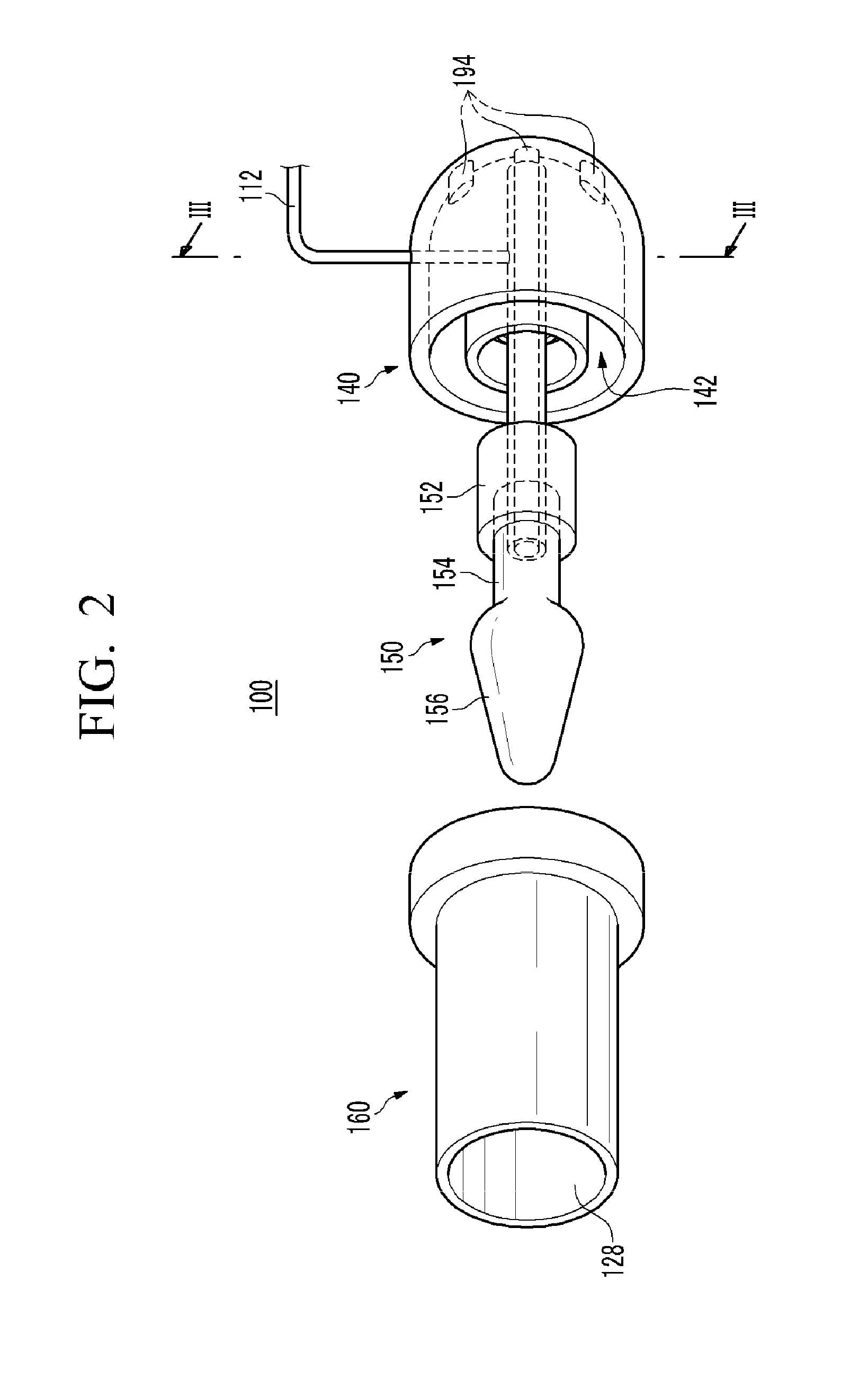
[0120]Referring to FIGS. 7 to 9, the plasma burner 100 further includes flow disturbance members 174, 177, and 179 around the flame vent 128 of the reaction furnace 160. The flow disturbance members 174, 177, and 179 may be differently formed, as shown in FIGS. 7 to 9.

[0121]Referring to FIG. 7, the flow disturbance member 174 is formed to protrude from an external circumference of the reaction furnace 160 at the flame vent 128. The flow disturbance member 174 gathers and stabilizes a flame that is projected to the flame vent 128 by flowing an exhaust gas between an external circumferential surface of the reaction furnace 160 and the exhaust conduit 40.

[0122]Referring to FIG. 8, the flow disturbance member 177 is disposed apart from the front of the flame vent 128. The flow disturbance member 177 may be formed in a circular strip having an interior diameter greate...

third exemplary embodiment

[0128]Further, the seventh exemplary embodiment illustrates a case where heat exchangers 132, 134, and 136 are provided to the second exemplary embodiment, and the case can be equally applied to the first exemplary embodiment, the third exemplary embodiment to the sixth exemplary embodiment, and the eighth exemplary embodiment.

[0129]FIG. 11 is a cross-sectional view of a plasma burner according to an eighth exemplary embodiment of the present invention.

[0130]Referring to FIG. 11, the electrode 150 includes a penetrating third passage 159 that is formed. The third passage 159 directly connects a heat-absorbing chamber 156 to the inside of a reaction furnace 160. That is, while most of the mixed gas passes through the second passage 154b, the mixture chamber 142, and the mixture gas nozzle 166, the third passage 159 directly passes a part of the mixed gas from the heat-absorbing chamber 156 to the reaction furnace 160. Therefore, the third passage 159 can supply a large amount of fuel...

second exemplary embodiment

[0131]Further, the eighth exemplary embodiment illustrates a case in which the third passage 159 is formed in the first exemplary embodiment, and the case can be equally applied to the second exemplary embodiment to the seventh exemplary embodiment.

[0132]FIG. 12 is a cross-sectional view of a plasma burner according to a ninth exemplary embodiment of the present invention.

[0133]Referring to FIG. 12, an exhaust gas guide 181 is formed around exhaust gas inlets 194. The exhaust gas guide 181 guides exhaust gas to the exhaust gas inlet 194 through an opening having a wider area than a distribution area of the exhaust gas inlets 194 that are distributed in the base 140 and a shape that becomes gradually narrow from the opening.

[0134]The exhaust gas guide 181 includes a first exhaust gas guide 181a and a second exhaust gas guide 181b according to the corresponding exhaust gas inlets 194. The first exhaust gas guide 181a is formed around the exhaust gas inlet 194 to induce an exhaust gas ...


PUM

PropertyMeasurementUnit
distancesaaaaaaaaaa
diameteraaaaaaaaaa
temperatureaaaaaaaaaa

Abstract

A plasma burner and a diesel particulate filter (DPF) trap that can effectively oxidize and remove a particulate material (PM) within an exhaust gas by preheating fuel and mixing the fuel with the exhaust gas are provided. The DPF includes: a filter that is connected to an exhaust conduit at a side opposite to that of an engine; a plasma burner that is provided within the exhaust conduit between the engine and the filter, and that includes a fuel inlet that supplies fuel and a flame vent that projects a flame by a plasma discharge, and that heats exhaust gas; and a fuel inflow conduit that connects the fuel inlet and a fuel tank.

Description

CROSS-REFERENCE TO RELATED APPLICATION[0001]This application claims priority to and the benefit of Korean Patent Application Nos. 10-2007-0076387, 10-2007-0078579, 10-2007-0078580, 10-2007-0078581, and 10-2007-0133306 filed in the Korean Intellectual Property Office on Jul. 30, 2007, Aug. 6, 2007, Aug. 6, 2007, Aug. 6, 2007, and Dec. 18, 2007 the entire contents of which are incorporated herein by reference.BACKGROUND OF THE INVENTION[0002](a) Field of the Invention[0003]The present invention relates to a plasma burner and a diesel particulate filter trap. More particularly, the present invention relates to a plasma burner and a diesel particulate filter trap that can effectively oxidize and remove particulate materials (PM) within exhaust gas by preheating fuel and mixing the fuel with the exhaust gas.[0004]The present invention relates to a plasma burner and a diesel particulate filter trap that can effectively oxidize and remove PMs within an exhaust gas by providing and preheati...

Claims


Application Information

Patent Timeline
Patent Type & Authority Patents(United States)
IPC IPC(8): B01D46/00
CPCF01N3/023F01N3/025F01N3/0253F01N3/0275F01N3/035F01N3/106F01N13/0097F01N3/36H05H1/24F01N3/30F01N2240/14F01N2240/28F01N2390/02H05H1/48
Inventor LEE, DAE-HOONKIM, KWAN-TAESONG, YOUNG-HOONCHA, MIN-SUKLEE, JAE-OK
Owner KOREA INST OF MACHINERY & MATERIALS
Learn More