Camera auto-calibration by horizon estimation

a technology of auto-calibration and horizon estimation, applied in the field of camera auto-calibration by horizon estimation, can solve the problems of inaccurate overlaid vehicle trajectory graphics on the camera image, inability of camera systems to provide camera calibration, and inability to provide camera calibration. to achieve the effect of reducing nois

Inactive Publication Date: 2012-09-04
GM GLOBAL TECH OPERATIONS LLC
View PDF1 Cites 20 Cited by
  • Summary
  • Abstract
  • Description
  • Claims
  • Application Information

AI Technical Summary

Benefits of technology

[0008]In accordance with the teachings of the present invention, a system and method are disclosed for estimating the horizon in an image of a camera to provide camera auto-calibration in the pitch direction. The method includes taking an image of a scene and generating a texture map of the image using horizontal edge detection analysis to locate horizontal edges in the scene. The method also includes providing a motion map by providing image differencing between subsequent images to find areas in the scene with no motion while the vehicle is moving. The texture map and the motion map are combined to identify the candidate areas in the image that do not move and contain horizontal edges. A horizontal projection is generated from the combined map by counting white dots in the candidate area in the map in the horizontal direction. The horizontal projection is smoothed to eliminate noise and the location of the horizon is estimated in the image by identifying the maximum peak in the horizontal projection. The estimated horizon can then be used in the auto-calibration process to calibrate the camera.

Problems solved by technology

Some known camera systems do not provide camera calibration, but revert to a default value that may provide a couple of degrees of error.
However, these calibration techniques are typically time consuming and must be performed at a service location.
This change can cause overlaid graphics of vehicle trajectory on the camera image to be inaccurate.
However, known camera calibration techniques that rely on horizon estimation are typically inaccurate and unreliable.

Method used


Image

  • Camera auto-calibration by horizon estimation
  • Camera auto-calibration by horizon estimation
  • Camera auto-calibration by horizon estimation

Examples


Embodiment Construction

[0012]The following discussion of the embodiments of the invention directed to a system and method for providing an estimation of the horizon in an image from a camera for camera auto-calibration in the pitch direction is merely exemplary in nature, and is in no way intended to limit the invention or its applications or uses. For example, the present invention has particular application for calibrating a vehicle camera. However, as will be appreciated by those skilled in the art, the present invention will have application for cameras other than vehicle cameras.

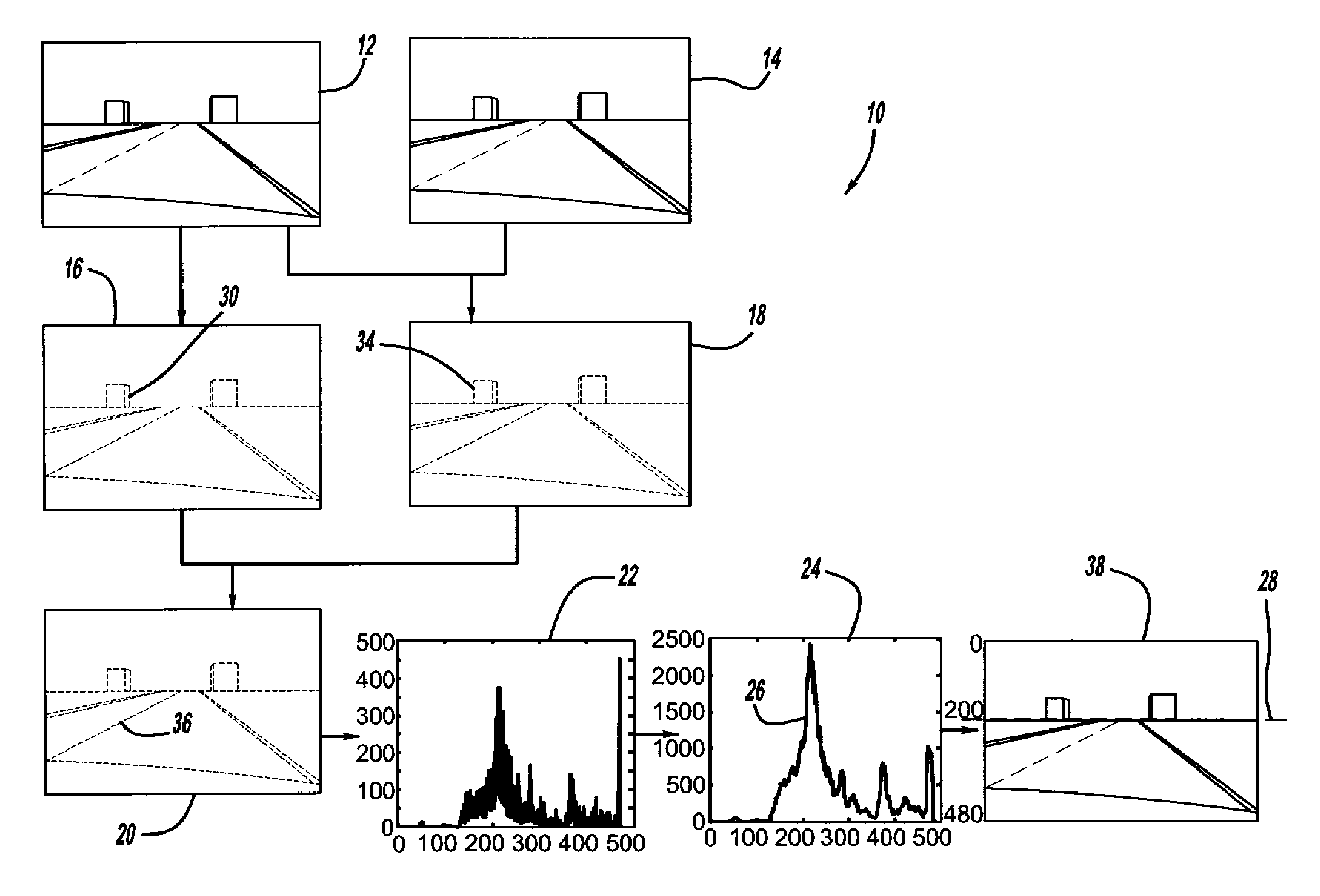
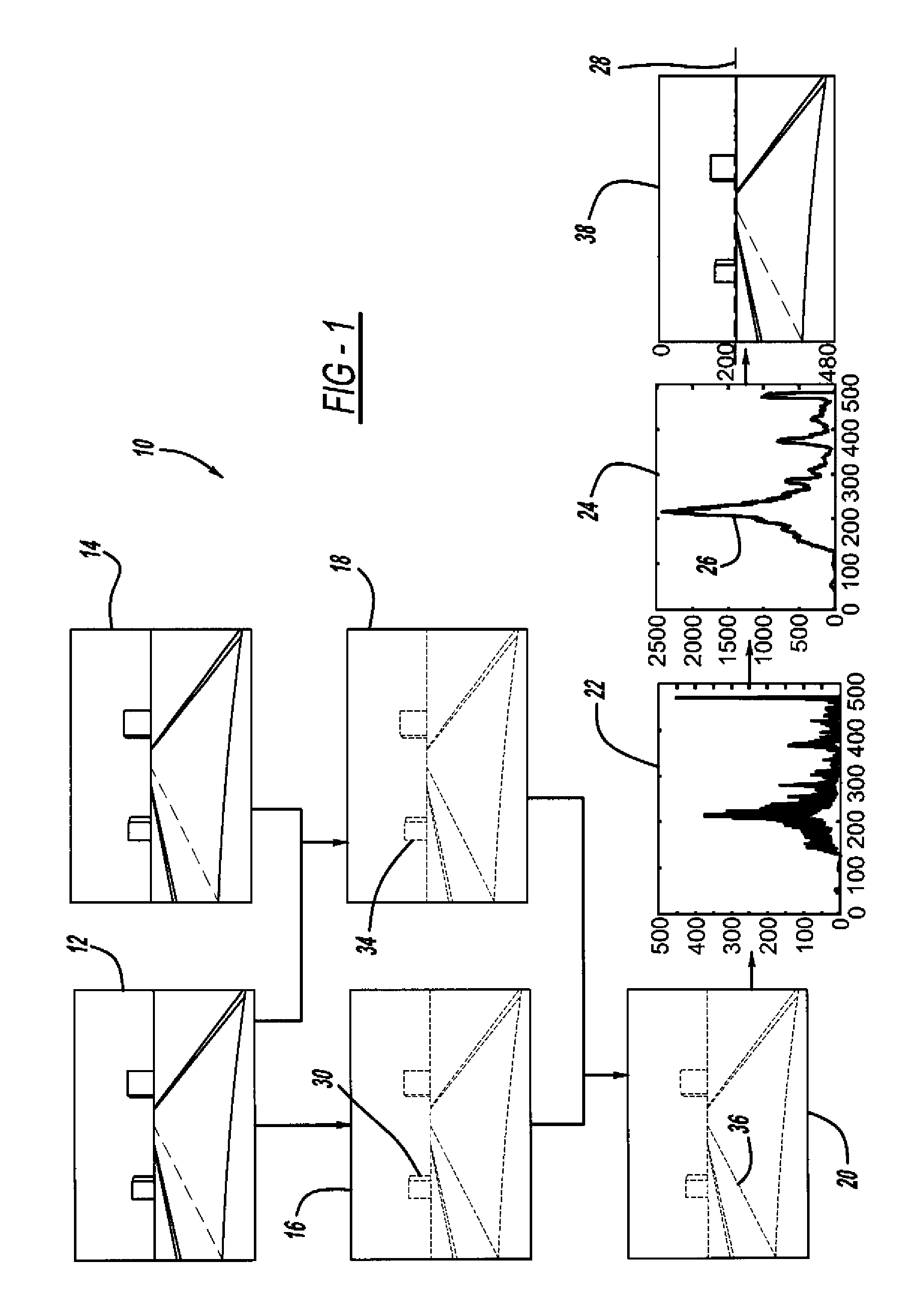
[0013]FIG. 1 is a flow chart diagram 10 showing a method for estimating a horizon in an image of a camera. A camera image 12 is shown at time k and a camera image 14 is shown at time k+1 of a road in front of a vehicle. As will be discussed below, the method estimates the horizon in the images 12 and 14, which is basically a line that contains many horizontal edges where the sky and road intersect. The horizon is basically th...


PUM


Abstract

A method for estimating the horizon in an image of a camera to provide camera auto-calibration in the pitch direction. The method includes taking an image of a scene and generating a texture map of the image using horizontal edge detection analysis to locate horizontal edges in the scene. The method also includes providing a motion map by providing image differencing between subsequent images to find areas in the scene with no motion while the vehicle is moving. The texture map and the motion map are combined to identify the areas in the image that do not move and contain horizontal edges. A horizontal projection is generated from the combined map by counting white dots in the map in the horizontal direction. The horizontal projection is smoothed to eliminate noise and the location of the horizon is estimated in the image by identifying the maximum peak in the horizontal projection.

Description

BACKGROUND OF THE INVENTION[0001]1. Field of the Invention[0002]This invention relates generally to a system and method for providing an estimation of the horizon in an image from a camera and, more particularly, to a system and method for providing an estimation of the horizon in an image from a camera for calibrating the camera in the pitch direction.[0003]2. Discussion of the Related Art[0004]Modern vehicles sometimes include one or more camera's that provide back-up assistance, take images of the vehicle driver to determining driver drowsiness or attentiveness, provide images of the road as the vehicle is traveling for collision avoidance purposes, provide structure recognition, such as roadway signs, etc. For those applications where graphics are overlaid on the camera images, it is critical to accurately calibrate the position and orientation of the camera with respect to the vehicle. Because of manufacturing tolerances, a separate end-of-line camera calibration, or aftermarke...

Claims


Application Information

Patent Timeline
Patent Type & Authority Patents(United States)
IPC IPC(8): H04N7/18H04N5/228G06K9/00
CPCG06K9/4647G06T7/0042G06T2207/30256G06T2207/20068G06T2207/10016G06T7/73G06V10/507
Inventor ZHANG, WENDENAIK, SANJEEV M.
Owner GM GLOBAL TECH OPERATIONS LLC
Why Eureka
Try Eureka