Leak detector for heat exchanger

a technology of leak detector and heat exchanger, which is applied in the direction of measuring devices, instruments, structural/machine measurement, etc., can solve the problems of pressure build-up in the container above the water, and achieve the effects of convenient removal, quick installation, and low cos

Active Publication Date: 2012-09-11
SANDERS LEON
View PDF12 Cites 17 Cited by
  • Summary
  • Abstract
  • Description
  • Claims
  • Application Information

AI Technical Summary

Benefits of technology

[0010]The device is adapted for use outside the exchanger system as a simple and temporary leak detector. Thus, it may be used with any heat exchanger design by simply connecting the detector to a port on one side of the heat exchanger, supplying air pressure to a port on the other side and sealing all remaining ports. It is then easily removed for normal operation of the heat exchanger. Because air can be used to pressurize the first side of the heat exchanger and water can be used in the container, the detector is inexpensive to use and quick to install.

Problems solved by technology

Therefore gas released from the bubbles causes a pressure build-up in the container above the water.

Method used


Image

  • Leak detector for heat exchanger
  • Leak detector for heat exchanger
  • Leak detector for heat exchanger

Examples


Embodiment Construction

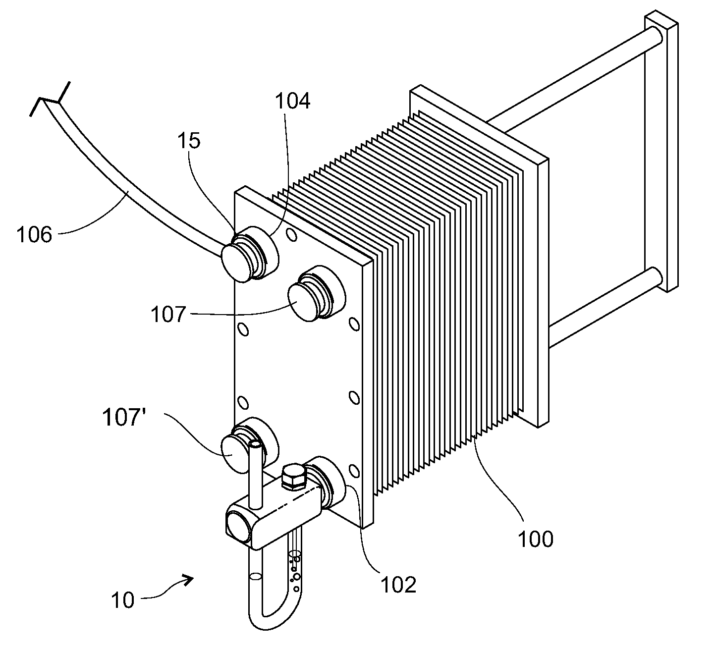
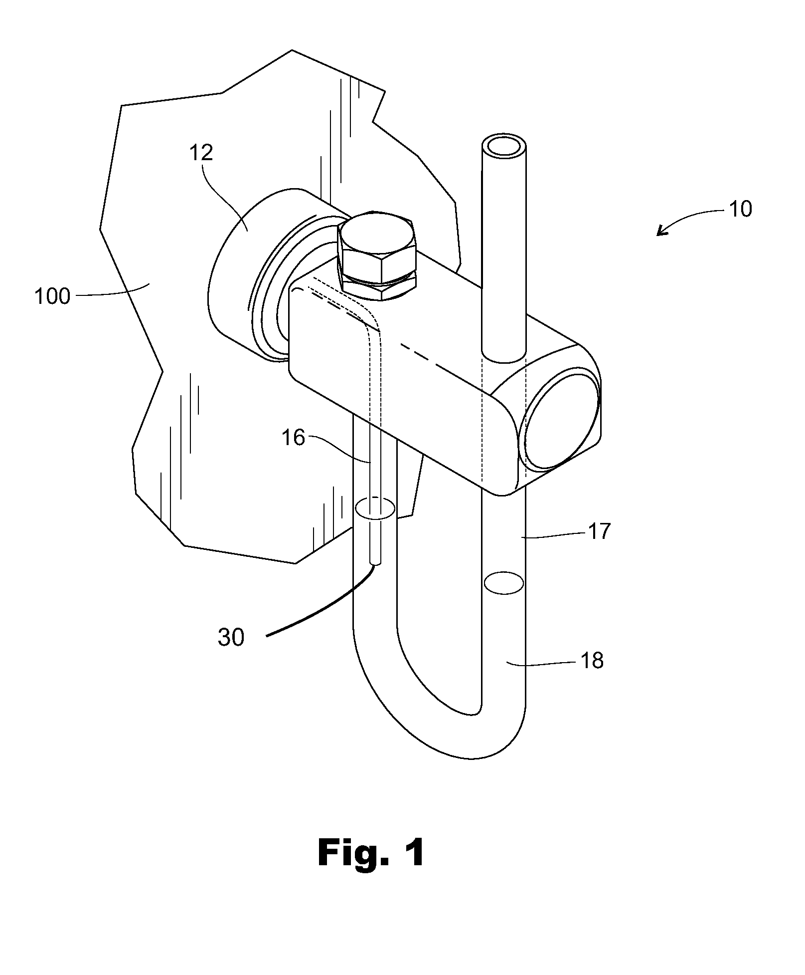
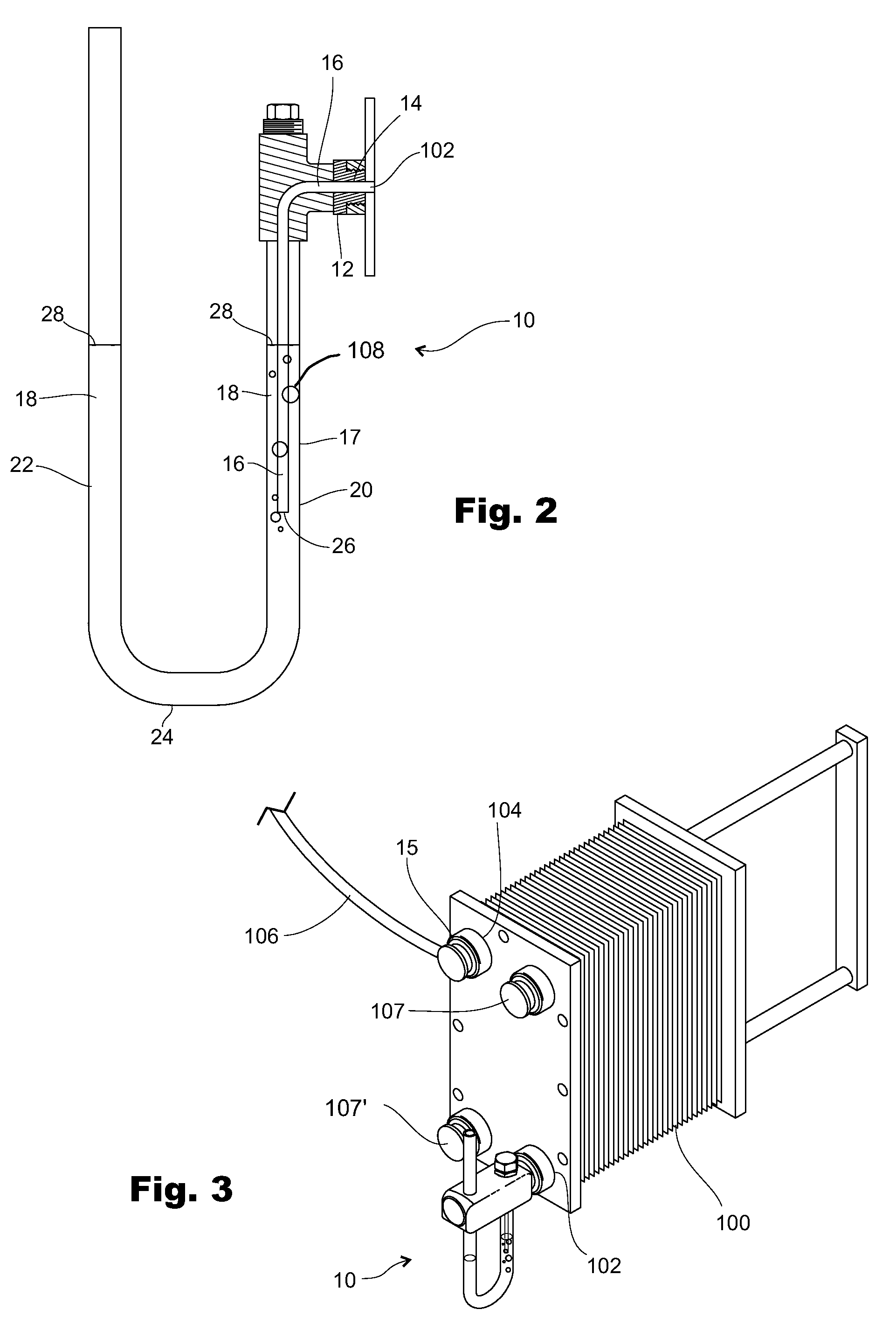
[0014]The gas leak detector 10 of the present invention for use with a heat exchanger 100 comprises a modified port plug 12 adapted to fit in a first heat exchanger port 102 that provides access to a heat exchanger's first side (not shown), with a hole 14 through the modified plug 12. A second port plug 15 connects to second heat exchanger port 104 to which a supply of pressurized air 106 is connected. The second heat exchanger port 104 provides access to a heat exchanger second side (not shown). A tube 16 extends from the hole 14 into a container 17 that can be filled with a liquid 18, typically water.

[0015]The container 17 is a generally U-shaped with first and second legs 20, 22 extending upward from a bottom 24. The first leg 20 connects to the modified plug 12 with an air tight seal. The tube 16 extends from the modified plug 12 into the first leg 20 of the U-shaped container 17 to a tube end position 26 below a position 28 to which water, or other equivalent liquid, is filled ...


PUM


Abstract

A heat exchanger leak detector employs a bubble detector to detect gas pressure build up in a heat exchanger second side from leakage of pressurized gas introduced in a heat exchanger first side.

Description

BACKGROUND[0001]1. Field of the Invention[0002]This invention relates to detection of leaks in heat exchangers, and more specifically to visible detection of a leak from one heat exchanger side to the other heat exchanger side using gas pressure build-up to create bubbles in a liquid outside the heat exchanger.[0003]2. Prior Art[0004]Heat exchangers comprise a first side, sometimes referred to as a product side, and a second side, sometimes referred to as a media side, in close contact with the first side. Plate heat exchangers that comprise a number of plates closely packed in series with fluids flowing through them while maintaining the two sides separate. Plate heat exchangers are commonly used in food processing where it is imperative that the fluids from the two sides remain separate, that is, that there are no leaks between the two heat exchanger sides that could cause cross contamination. Cross contamination occurs when a crack or pinhole develops, allowing fluids on one side...

Claims


Application Information

Patent Timeline
Patent Type & Authority Patents(United States)
IPC IPC(8): G01M3/02
CPCG01M3/106G01M3/3245
Inventor SANDERS, LEON
Owner SANDERS LEON
Why Eureka
Try Eureka