Retraction apparatus and method of use

a technology of retracting apparatus and tissue, which is applied in the field of retracting apparatus and method, can solve the problems of difficult use, easy adjustment, and suffering of existing surgical retracting apparatus, and achieve the effects of simple pivoting motion, simple use, and convenient and rapid positioning

Inactive Publication Date: 2012-09-11
PIONEER SURGICAL TECH INC
View PDF80 Cites 33 Cited by
  • Summary
  • Abstract
  • Description
  • Claims
  • Application Information

AI Technical Summary

Benefits of technology

[0007]In accordance with one aspect of the invention, a retraction apparatus is provided having a locking mechanism for locking a tissue engagement member, such as retractor blade, to a slider member at a selected depth in an incision. The locking mechanism has a pivot lever that is pivotal between an unlocked position that allows the retractor blade to be slidably adjusted upwardly or downwardly and a locked position that fixes the retractor blade at the selected depth. As is apparent, rather than having to depress spring-loaded pins or rotate worm gears to adjust the retractor blade, the pivot lever permits the retractor blade to be easily and rapidly positioned at a desired depth within an incision and fixed thereat with a simple pivoting motion. Further, utilizing a pivot lever to control the movement of the retractor blade provides an intuitive manner of locking the retractor blade that is simple to use.
[0008]In one form, pivoting the pivot lever to the locked position creates a frictional engagement between the slider member and the retractor blade that fixes the slider member and the retractor blade together. This frictional engagement avoids reliance on complicated mechanical interfaces that may become fouled during surgery. The locking mechanism may also include a locking member that is preferably flush with an end of the slider member when the pivot lever is in the unlocked position. Before the pivot lever is pivoted to the locked position, the retractor blade may be slidably mounted onto the slider member and positioned at the desired depth within the incision. Pivoting the pivot lever presses the locking member against a contact surface of the retractor blade and shifts the retractor blade against the slider member to fix the retractor blade at the desired depth within the incision. Preferably, the slider member and the retractor blade have a slide connection therebetween that permits the retractor blade to slide upwardly and downwardly relative to the slider member. With the pivot lever in the unlocked position, the retractor blade can be positioned at an infinite number of positions along the connection to conform the blade closely to the anatomy of a patient.
[0011]In another aspect of the invention, a retraction apparatus is provided having a retractor body straight portion with a substantially flat surface configured to be placed adjacent a bone. A pair of opposed retractor body portions are connected at either end of the straight portion and extend transversely to the straight portion. This way, slider members received within the opposed portions retract in directions transverse to the straight portion and avoid striking the bone. If the bone is relatively narrow, the retractor blades may retract to a position wider than the bone such that the retractor blades and retracted soft tissues are positioned on opposing sides the bone. Soft tissue retracted by the blades is relatively taught, so positioning the blades on opposing sides of the bone stretches the soft tissue against the bone and widens the operating channel toward the bone.
[0012]The retractor body preferably has a bridge portion that extends between the opposed retractor body portions and orients them at an incline relative to each other. The incline produces a V-shape between the opposed retractor body portions and positions the slider members at an angle relative to one another. Unlike prior configurations with retractor blades that retract in opposite directions along a shared axis, the transverse paths of the slider members permit both slider members to retract in a similar direction, such as toward a bone adjacent the retractor body. This configuration is desirable, as a pair of retractor blades retracting toward the bone tends to position the surgical channel closer to the bone than would a single retractor blade retracting toward the bone.
[0013]In some instances, it is desirable to have a minimum number of blades to improve operability in tight working environments. To this end, the retractor apparatus may employ a third slider member that retracts in a direction transverse to the paths of the other slider members so that the size of the incision may be maximized using only three retractor blades. Specifically, with the flat surface of the retractor body straight portion positioned adjacent a bone, the pair of retractor blades associated with the opposed retractor body portions retract tissue toward either side of the bone. The third slider member is disposed in the retractor body bridge portion such that the connected retractor blade retracts soft tissue away from the bone. Thus, the soft tissue is retracted toward either side of the bone as well as away from the bone to maximize the retracted incision opening with only three retractor blades.
[0014]Another feature of the retractor body is that the pair of opposed retractor body portions may be pivotal relative to the straight portion about transverse pivot axes. Pivoting the retractor body portions upward “toes out” the ends of the retractor blades so that there is greater room to operate deeper within the incision. Further, when the flat surface of the retractor body straight portion is positioned adjacent a bone, toeing out the retractor blades may press soft tissue against the bone to create even greater room within the incision.

Problems solved by technology

However, existing surgical retractors continue to suffer from a number of shortcomings which make them difficult to use.
One such problem is the ability to easily adjust the depth of the retractor blades within an incision to avoid striking bones when the blades retract.
However, these systems are difficult to adjust and require tools to manipulate the position of the retractor blades.
As is apparent, this approach is time-consuming and requires a significant amount of tool rotation to individually adjust the retractor blades.
Another problem with existing surgical retractors is the difficulty involved with connecting or removing retractor blades.
This approach is clearly problematic, as having to use an instrument to adjust or remove each retractor blade unduly prolongs surgery.
Further, the plurality of holes in the retractor blade restricts the blade to a discrete number of positions along the slider, which limits the ability of a surgeon to adjust the blade depth to conform to a patient's anatomy.
Retracting soft tissue in close proximity to a bone poses yet another problem for standard surgical retractors because the retractor blades cannot retract the tissue toward the bone to position the surgical channel near the bone.
With the retractor blades in the retracted position, the thickness of the straight side retractor blade and its connection to the support structure limit how far the surrounding tissue can be retracted toward the bone.
Also, if the bone is elevated above the surrounding anatomy, the straight side support structure may strike the bone, which limits the size of the enlarged opening.

Method used


Image

  • Retraction apparatus and method of use
  • Retraction apparatus and method of use
  • Retraction apparatus and method of use

Examples


Embodiment Construction

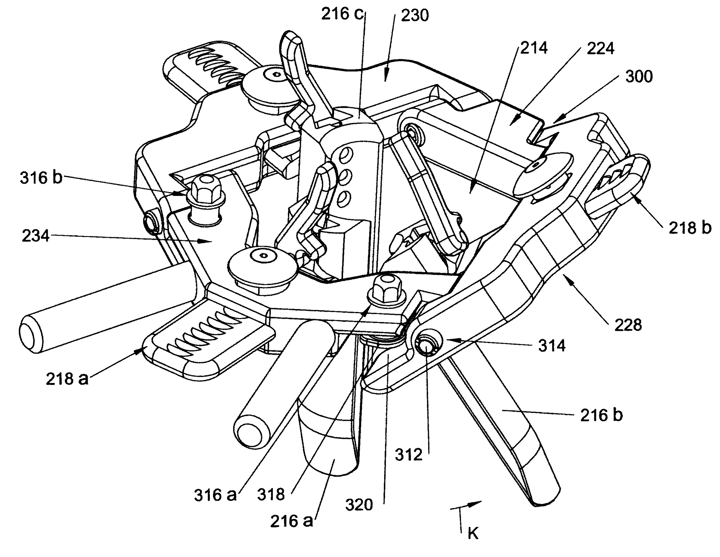
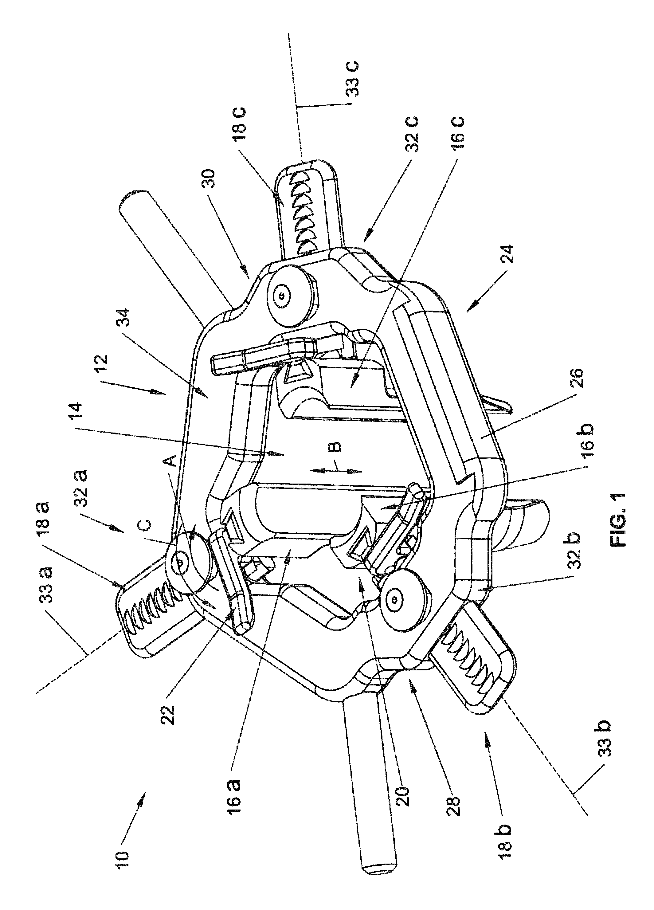
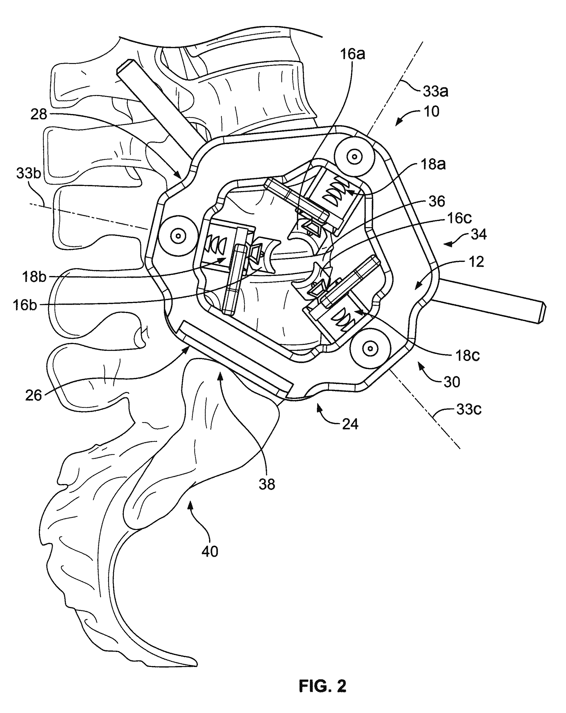
[0033]Referring initially to FIG. 1, an access retractor 10 in accordance with the present invention is depicted in a representative embodiment and set up with the apparatus 10 including a frame or body 12 with a large retraction opening 14 centrally located for accessing a surgical site. Inside the opening 14 are located a number of tissue engaging members, such as in the form of retractor blades 16a, 16b, and 16c, which are used to expand an incision and are shown in a fully retracted position. Slider assemblies 18a, 18b, 18c are slidably mounted to the retractor body 12 and connect the blades 16 thereto.

[0034]Preferably, each slider assembly 18 has a locking mechanism 20 for fixing the blade 16 to the slider assembly 18. The locking mechanism 20 includes a pivot or clamping lever, such as a handle 22, which may be pivoted in direction A to an unlocked position that allows the blade 16 to be connected or removed relative to the slider assembly 18. When the handle 22 is in the unlo...


PUM


Abstract

A retraction apparatus and method are provided including slider assemblies for being slidably connected to a retractor body with end portions of the slider assemblies disposed within a central retractor opening. A retractor blade is slidably connected to one of the slider assembly end portions such that the depth of the retractor blade can be readily adjusted. Once the retractor blade is at the desired depth within the incision, a handle is pivoted to a locked position to fix the blade relative to the slider assembly. A cantilever lock between the blade and the slider assembly pivots the blade relative to the slider assembly to fix the blade thereto. In one form, the retractor body has a substantially flat surface configured to be placed adjacent a bone and slide connections which position slider assemblies such that the connected blades avoid contact with the bone during retraction.

Description

CROSS-REFERENCE TO RELATED APPLICATION[0001]This application claims the benefit of U.S. Provisional Patent Application Ser. No. 61 / 057,639, filed May 30, 2008, which is hereby incorporated by reference as if fully set forth herein.FIELD OF THE INVENTION[0002]The invention relates generally to a retractor and method for providing access to a surgical site and, more particularly, a retractor and method for retracting tissue during a surgical procedure.BACKGROUND OF THE INVENTION[0003]Surgical retractors are devices that utilize tissue engaging members, such as retractor blades, to increase the size of an incision and provide access to a surgical site. Retractors permit a surgeon to retract soft tissues surrounding the incision and obtain a clear view of the operating site during a procedure. By retracting the tissue surrounding the incision to form an enlarged surgical channel, a relatively small incision may be used which minimizes trauma to the patient and shortens recovery time. Ho...

Claims


Application Information

Patent Timeline
Patent Type & Authority Patents(United States)
IPC IPC(8): A61B1/32
CPCA61B17/0293
Inventor WHITE, JOHNBERMAN, PHILLIP J.GEPHART, MATTHEW P.
Owner PIONEER SURGICAL TECH INC
Why Eureka
Try Eureka