Capacitance difference detecting circuit and capacitance difference detecting method

a capacitance difference and detection circuit technology, applied in the direction of resistance/reactance/impedence, pulse technique, instruments, etc., can solve the problems of low yield or high cost of examining product defects, different problems of prior art capacitor type detectors, and inability to equalize capacitance, so as to achieve the effect of suppressing common model disturbance, capacitance difference, and improving psrr

Inactive Publication Date: 2012-09-11
ILI TECHNOLOGY CORPORATION
View PDF3 Cites 2 Cited by
  • Summary
  • Abstract
  • Description
  • Claims
  • Application Information

AI Technical Summary

Benefits of technology

[0011]Therefore, one objective of the present invention is to provide a capacitor detecting circuit and a capacitor detecting method, which can detect capacitance variation without detecting real capacitance values.
[0015]According to above-mentioned embodiments, capacitance variation can be detected without detecting real capacitance value, and the comparator offset can be ignored. Additionally, differential input can effectively suppress common model disturbance. Also, capacitance difference is not related with power source such that PSRR can be improved. Moreover, the utilization of only one comparator and a simple digital logic controller can save power and has the advantage of high resolution.

Problems solved by technology

However, a prior art capacitor type detector may has different problems.
For example, if the capacitor type detector is utilized as the touch sensing panel, the adhesion of ITO may cause non equal capacitance.
Additionally, an electronic apparatus may have the problem of parasitical capacitance, background capacitance or system distribution, which may cause low yield or high cost to examine product defect.
Besides, if the background capacitance is too large but the variance for detected capacitance of the capacitor type detector is too small (for example, the capacitance variation caused by finger touch), it will be hard to determine the variation of the detecting capacitance.
However, in the example shown in FIG. 2, most resolution bits of the ADC 201 are wasted on Cstray+Cs, such that the sensitivity and the dynamic range of detecting operation decrease.
Accordingly, error measurement may be caused due to parasitical capacitance, background capacitance or different kinds of noises.

Method used


Image

  • Capacitance difference detecting circuit and capacitance difference detecting method
  • Capacitance difference detecting circuit and capacitance difference detecting method
  • Capacitance difference detecting circuit and capacitance difference detecting method

Examples


Embodiment Construction

[0020]Certain terms are used throughout the description and following claims to refer to particular components. As one skilled in the art will appreciate, electronic equipment manufacturers may refer to a component by different names. This document does not intend to distinguish between components that differ in name but not function. In the following description and in the claims, the terms “include” and “comprise” are used in an open-ended fashion, and thus should be interpreted to mean “include, but not limited to . . . ”. Also, the term “couple” is intended to mean either an indirect or direct electrical connection. Accordingly, if one device is coupled to another device, that connection may be through a direct electrical connection, or through an indirect electrical connection via other devices and connections.

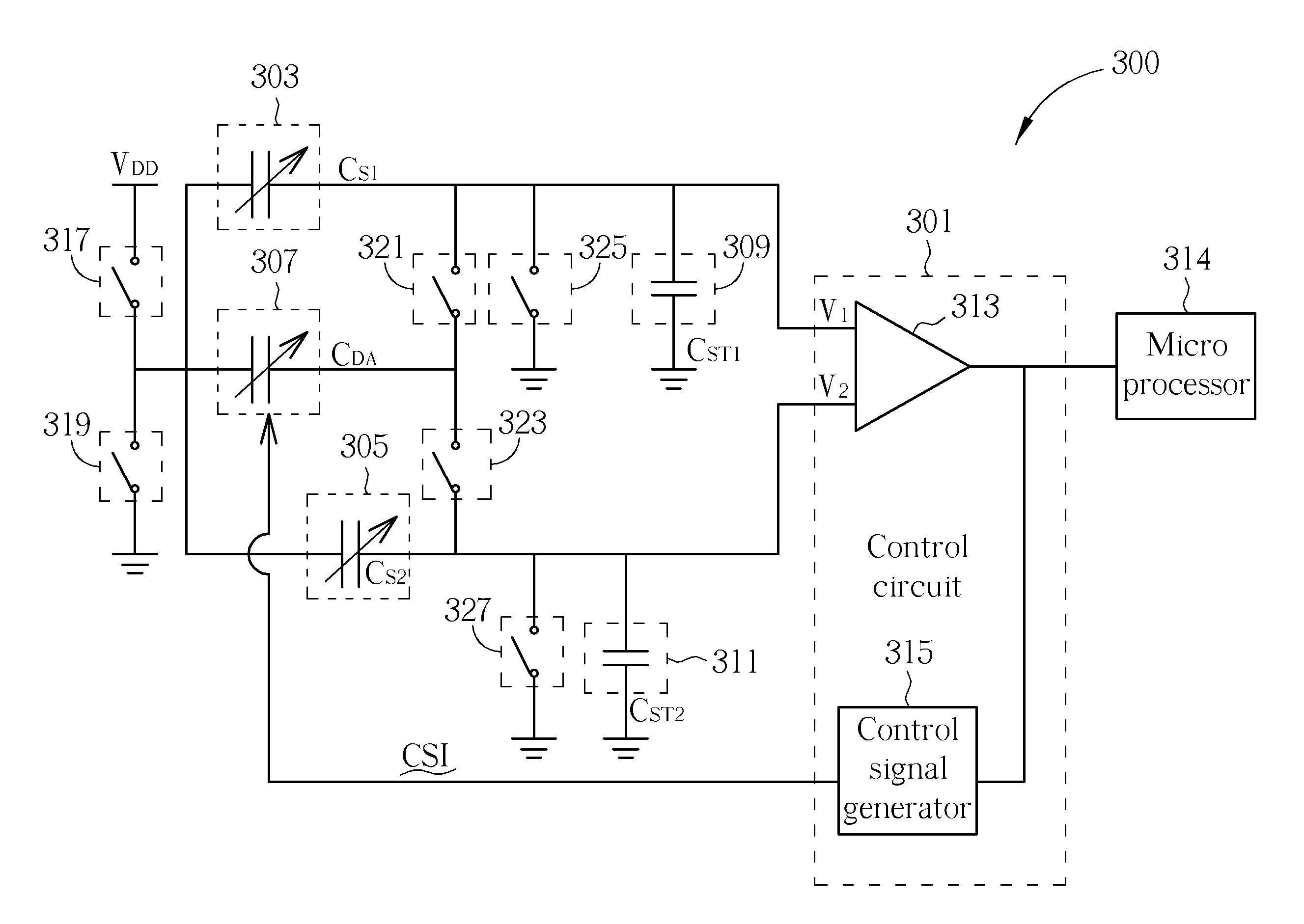
[0021]FIG. 3 is a schematic diagram illustrating a capacitance difference detecting circuit 300 according to an embodiment of the present application. The capacitance dif...


PUM


Abstract

A capacitance difference detecting circuit includes a control circuit, for generating a control signal according to a first voltage and a second voltage; a first capacitor to be detected; a second capacitor to be detected; a first constant capacitor, having a terminal coupled to the first terminal of the first capacitor to be detected and the first input terminal; a second constant capacitor, having a terminal coupled to the first terminal of the second capacitor to be detected and the second input terminal; a voltage control unit, cooperating with the first capacitor to be detected, the second capacitor to be detected, the first constant capacitor and the second constant capacitor to control the first voltage and the second voltage. The voltage control unit is an adjustable capacitor and a capacitance value of the adjustable capacitor is controlled by the control signal.

Description

BACKGROUND OF THE INVENTION[0001]1. Field of the Invention[0002]The present invention relates to a capacitance difference detecting circuit and a capacitance difference detecting method, and particularly relates to a capacitance difference detecting circuit and a capacitance difference detecting method that need not to measure real capacitance value of the capacitor to be detected.[0003]2. Description of the Prior Art[0004]In modern electronic apparatuses, the capacitor type detector, which is always applied to a touch sensing device such as a touch sensing panel, is a well know technology. However, a prior art capacitor type detector may has different problems. For example, if the capacitor type detector is utilized as the touch sensing panel, the adhesion of ITO may cause non equal capacitance. Additionally, an electronic apparatus may have the problem of parasitical capacitance, background capacitance or system distribution, which may cause low yield or high cost to examine produ...

Claims


Application Information

Patent Timeline
Patent Type & Authority Patents(United States)
IPC IPC(8): G01R27/26
CPCG01D5/24H03K17/962H03K2217/96074H03K2217/960745
Inventor LIN, KUN-CHIHWU, WEN-CHI
Owner ILI TECHNOLOGY CORPORATION
Why Eureka
Try Eureka