Saddle riding type vehicle

a riding type, saddle technology, applied in the direction of suspensions, instruments, cycles, etc., can solve the problems of difficult use troublesome operation of the lock mechanism, and manual operation of the rider's switch

Active Publication Date: 2012-09-11
YAMAHA MOTOR CO LTD
View PDF14 Cites 0 Cited by
  • Summary
  • Abstract
  • Description
  • Claims
  • Application Information

AI Technical Summary

Benefits of technology

[0011]According to a preferred embodiment of the present invention, the support mechanism is provided to support a pair of wheels to be movable up and down relative to the vehicle body. Thus, with leaning of the vehicle body, both of the wheels can contact the ground. The vehicle can therefore run by leaning the vehicle body at a time of making a turn, for example. The lean limiting mechanism is arranged to limit up-and-down motion of the pair of wheels so as to inhibit leaning of the vehicle body. Further, the controller controls the lean limiting mechanism based on the results of detection by the state detecting device. The lean limitation of the up-and-down motion of the pair of wheels and its cancellation are executed automatically, which relieves the rider of the need to make a special effort to operate the lean limiting mechanism. Since control of the lean limiting mechanism by the controller is based on vehicles states, the lean limitation of the up-and-down motion of the pair of wheels and its cancellation can be carried out properly. The rider can therefore travel lightly and comfortably.
[0036]According to this preferred embodiment of the present invention, the support mechanism can be simplified in construction.

Problems solved by technology

However, the conventional vehicle with such a construction has the following drawback.
It is bothersome for the rider to operate the switch manually in order to operate the lock mechanism.
It is especially bothersome to operate the lock mechanism when the vehicle runs at low speed before stopping or after starting.
There is an inconvenience that the lock mechanism is not easy to use in an actual traveling situation.

Method used


Image

  • Saddle riding type vehicle
  • Saddle riding type vehicle
  • Saddle riding type vehicle

Examples


Embodiment Construction

[0051]Preferred embodiments of the present invention will be described in detail herein after with reference to the drawings.

[0052]A saddle riding type vehicle according to a preferred embodiment of the present invention will be described herein after referring to the drawings.

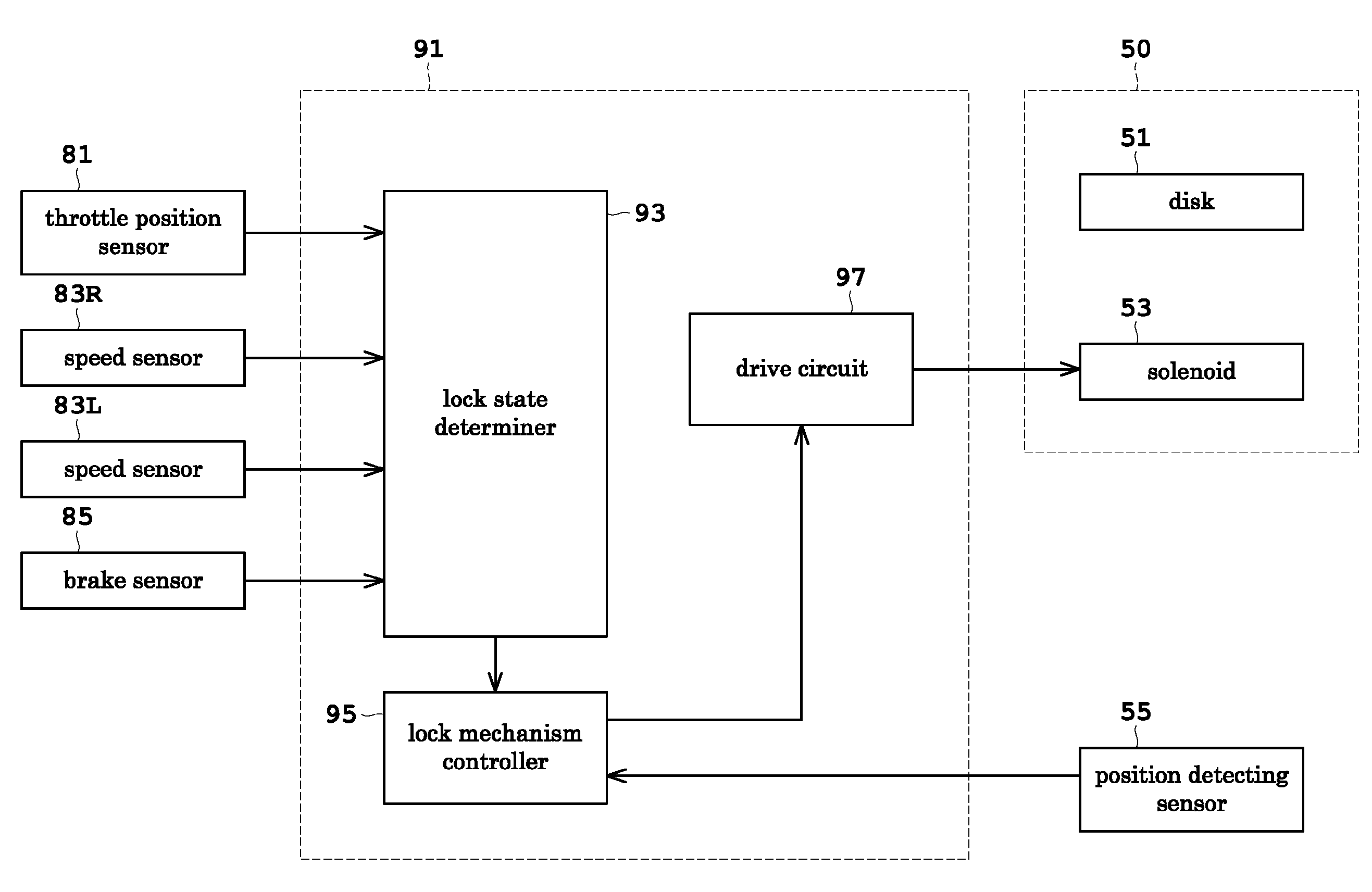
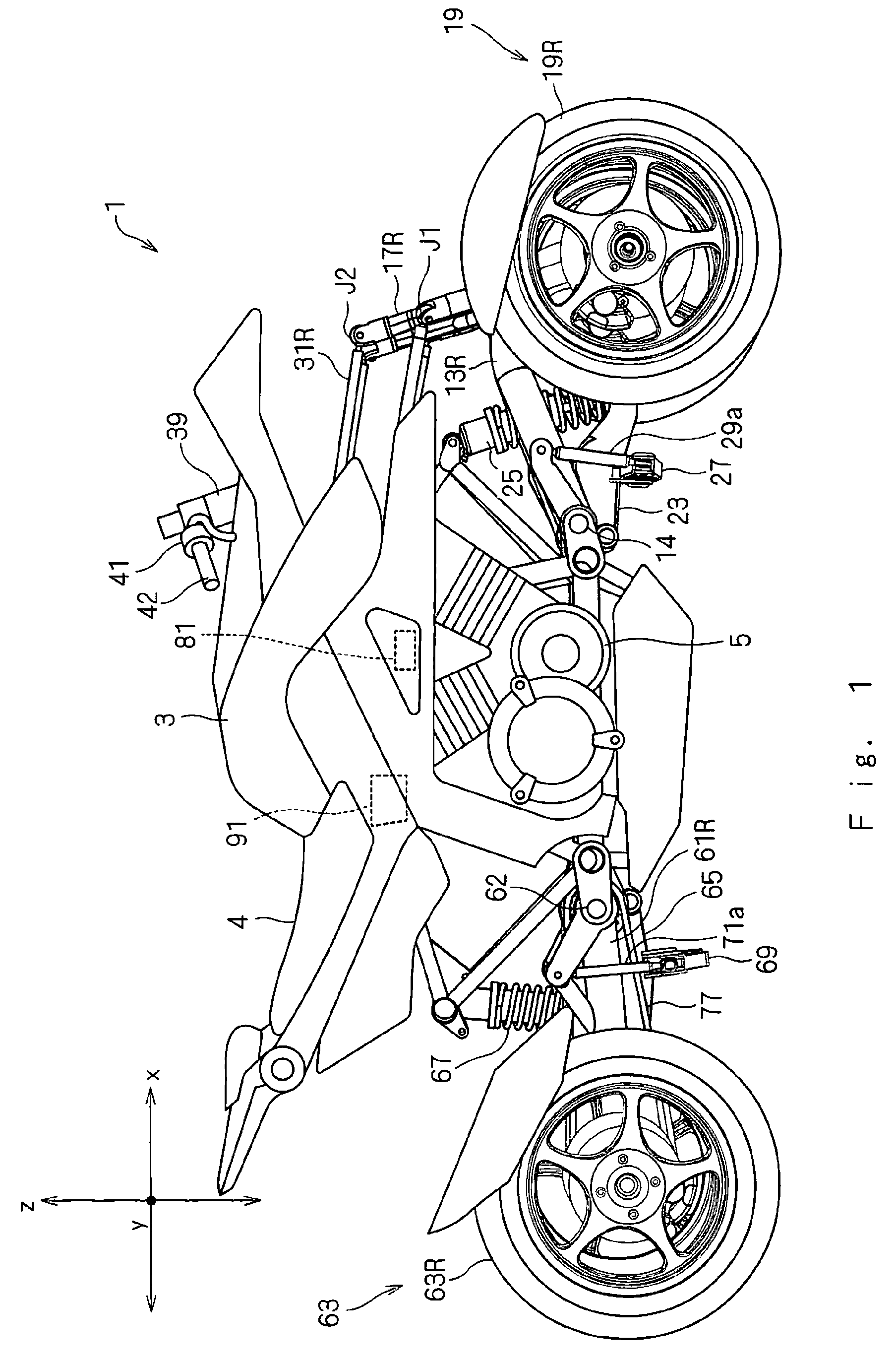
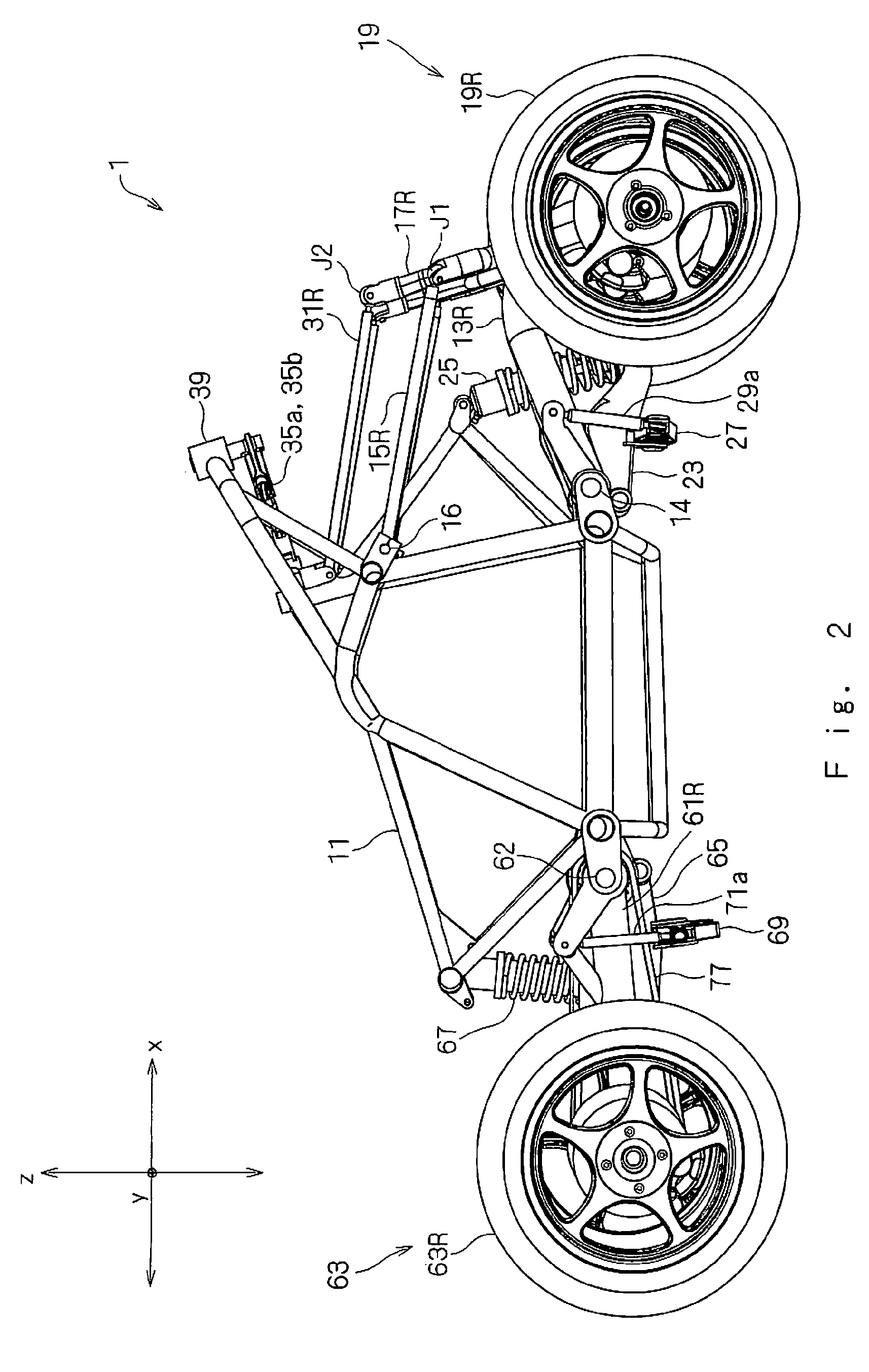
[0053]FIG. 1 is a side view showing an outward appearance of the saddle riding type vehicle according to the present invention. FIG. 2 is a side view showing an outline construction of the saddle riding type vehicle. FIG. 3 is a perspective view showing an outline construction of the saddle riding type vehicle. FIG. 4 is a front view of a principal portion showing a lock mechanism. FIG. 5 is a perspective view of the principal portion showing the lock mechanism. In the following description, the “right” and “left” refer to the sides seen from the rider seated on the saddle riding type vehicle. In FIGS. 1 and 2, the right side of the drawings corresponds to the front of the saddle riding type vehicle 1. In FIG....


PUM


Abstract

A saddle riding type vehicle includes a support mechanism arranged to support a pair of wheels to be movable up and down relative to a vehicle body, a lock mechanism connectable to the support mechanism and arranged to limit up-and-down motion of the pair of wheels, various sensors arranged to detect vehicle states, and a controller arranged to control the lock mechanism based on results of detection by the various sensors. The controller controls the lean limitation to the up-and-down motion of the pair of wheels and its cancellation automatically. The rider need not carry out a special control for operating the lock mechanism. In addition, the lock mechanism is controlled according to the vehicle states, which allows the rider to travel lightly and comfortably.

Description

BACKGROUND OF THE INVENTION[0001]1. Field of the Invention[0002]The present invention relates to a saddle riding type vehicle such as a three-wheeled or four-wheeled automotive vehicle having a pair of wheels at least at the front or rear of a vehicle body and being able to make turns by leaning the vehicle body.[0003]2. Description of the Related Art[0004]A saddle riding type vehicle has a pair of wheels located at both sides of the vehicle body at the front and / or rear of the vehicle body, and a support mechanism for supporting at least one pair of wheels to be movable up and down in substantially opposite directions relative to the vehicle body. The saddle riding type vehicle constructed in this way can make turns by leaning the vehicle body, as does a motorcycle (as disclosed in Japanese Unexamined Patent Publication No. 2004-359232, for example).[0005]Japanese Unexamined Patent Publication No. 2004-359232 discloses a three-wheeled automotive vehicle having a pair of wheels prov...

Claims


Application Information

Patent Timeline
Patent Type & Authority Patents(United States)
IPC IPC(8): G01M17/00G06F11/30G06F7/00G06F19/00G07C5/00B62K5/01B62K5/02B62K5/05
CPCB60G3/14B60G21/007B62K5/10B60G2300/124B60G2300/45
Inventor HARA, NOBUOWATANABE, KENICHIOOMURA, YASUHIRONONAKA, TAKAFUMI
Owner YAMAHA MOTOR CO LTD
Why Eureka
Try Eureka