Optical communication system having optical amplification function

a communication system and optical amplifier technology, applied in the field of optical amplifier function, can solve the problems of increasing the cost of purchase and installment, difficulty in reducing the cost of the system, and time-consuming maintenance and labor

a communication system and optical amplifier technology, applied in the field of optical amplifier function, can solve the problems of increasing the cost of purchase and installment, difficulty in reducing the cost of the system, and time-consuming maintenance and labor

US20070014574A1Inactive Publication Date: 2007-01-18SUMITOMO ELECTRIC IND LTD

Image

  • Optical communication system having optical amplification function
  • Optical communication system having optical amplification function
  • Optical communication system having optical amplification function

Examples


Embodiment Construction

[0009] The invention therefore has an object to provide an optical communications system capable of furnishing optical fibers with the optical amplification function.

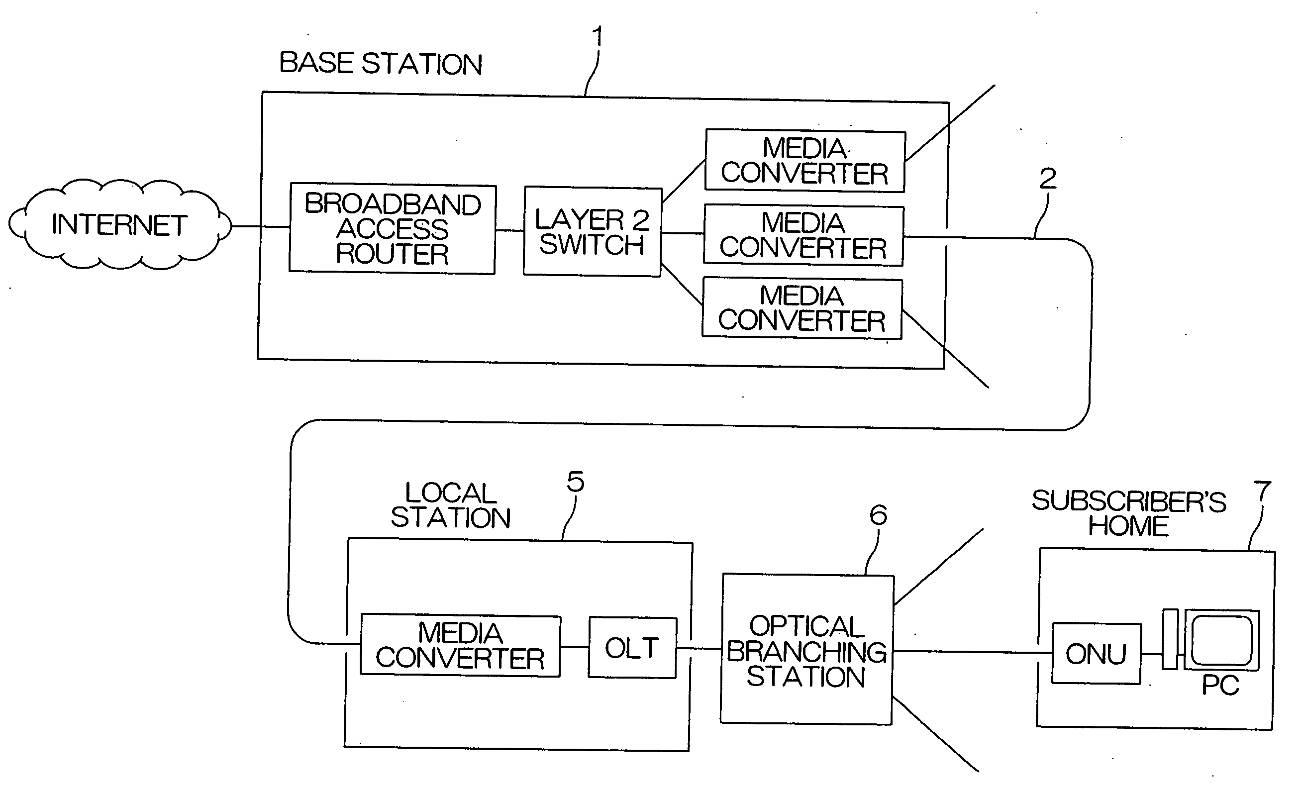
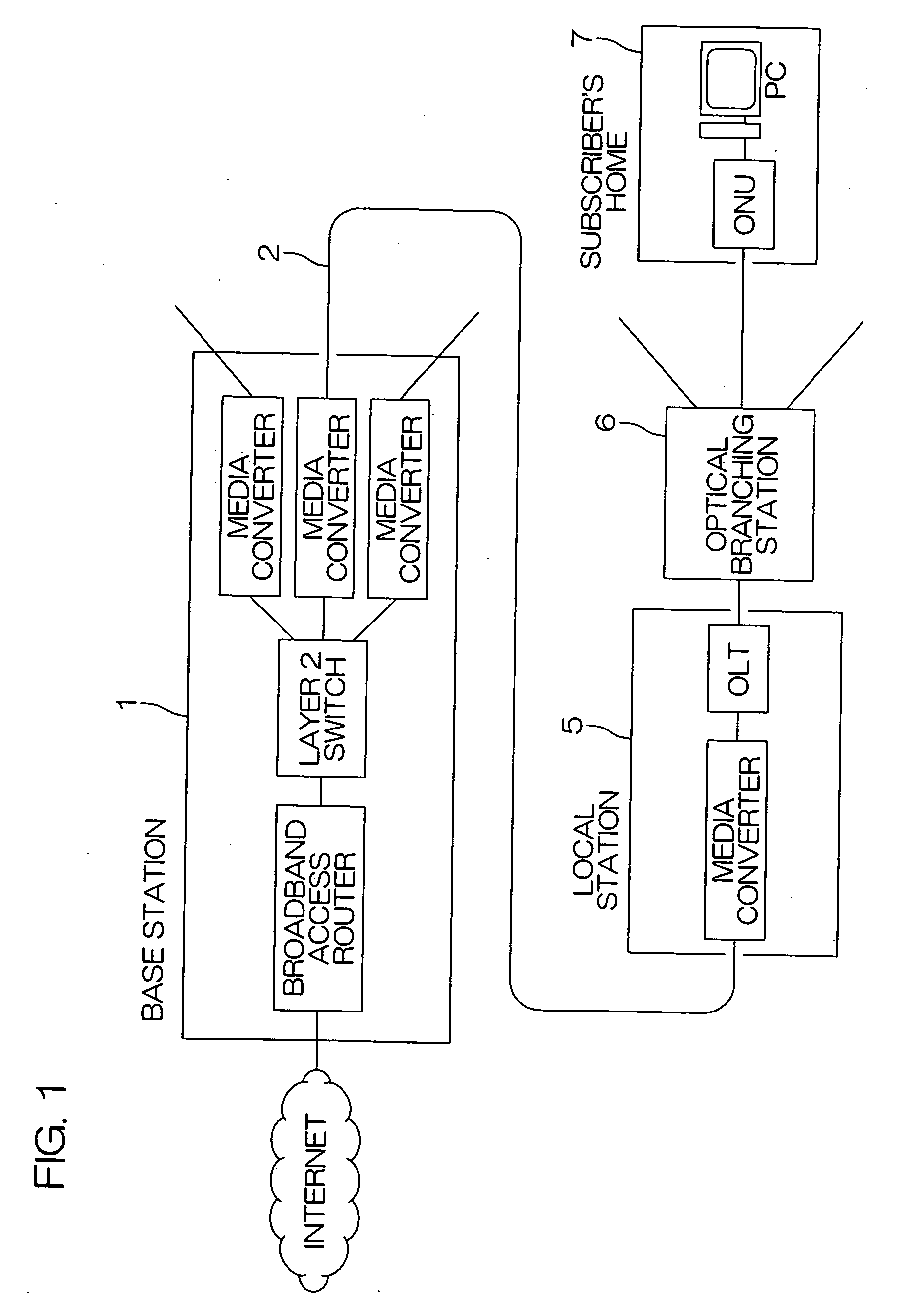
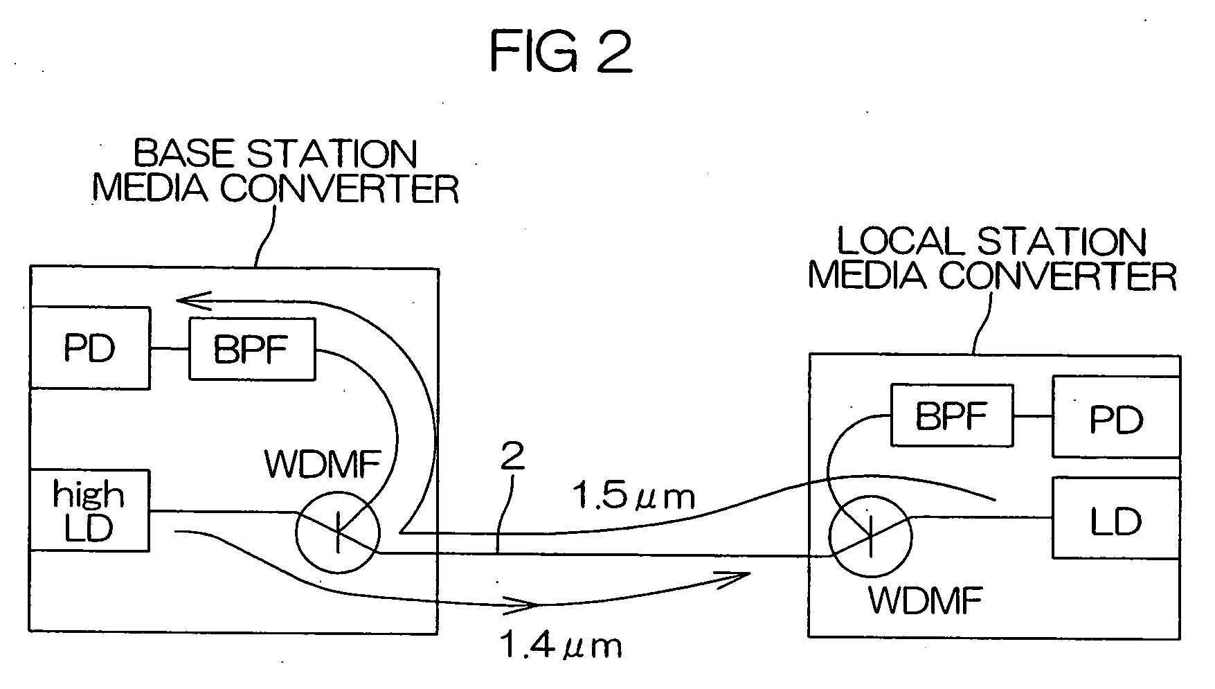
[0010] An optical communications system of the invention is characterized in that a wavelength of a light source for a signal that generates downstream signal light is set to a wavelength with an effect of Raman amplifying an upstream light signal that propagates through an optical fiber, and an upstream light signal transmitted between a base station and a local station is amplified in the optical fiber while the upstream light signal is propagating through the optical fiber.

[0011] According to this configuration, light for a signal having a wavelength with an effect of amplifying an upstream light signal is generated using the light source for a signal, and the light for a signal is transmitted to the local station via the optical fiber. It is thus possible to amplify upstream signal light traveling through the opti...


PUM


Abstract

In optical communications between a base station and a local station, the wavelength of a laser light source for a signal, high LD, in the base station that generates downstream signal light is set to a wavelength with an effect of Raman amplifying an upstream light signal that propagates through an optical fiber 2. In the optical fiber 2, an upstream light signal transmitted from the local station to the base station is amplified with the downstream signal light from the laser light source for a signal, high LD, while the upstream light signal is propagating through the optical fiber 2.

Description

FIELD OF THE INVENTION [0001] The present invention relates to an optical communications system in which a base station and a local station are connected using an optical fiber. [0002] The invention relates to an optical communications system, and more particularly, to a PON (Passive Optical Network) system in which a base station and an optical branching station equipped with a passive optical divider are connected using a backbone optical fiber, and the optical branching station and plural local stations are connected individually using branch optical fibers. BACKGROUND ART [0003] In a system enabling two-way communications between a base station and plural local stations using an optical data communications network, a network configuration (Single Star) connecting the base station and the respective local stations in a radial pattern using a single optical fiber for each local station is now put into practical use. With this network configuration, the system and the device config...

Claims


Application Information

Patent Timeline
18 Jan 2007
Publication
US20070014574A1
IPC
H04J14/00; H04B10/291
CPC
H04B10/2916; H04B10/25; H01S3/10; H01S3/30; G02F1/35
Inventors
YADA, KATSUHIRO