Radiator tube dimple pattern

a technology of dimple pattern and radiation tube, which is applied in the direction of indirect heat exchangers, laminated elements, lighting and heating apparatus, etc., can solve the problems of increasing the pressure drop of fluid flowing through the tube, increasing the pressure drop of fluid, and reducing the thermal efficiency of the heat exchanger. , to achieve the effect of maximizing the thermal efficiency of the heat exchanger and maximizing the durability of the tub

Active Publication Date: 2012-09-18
HANON SYST
View PDF23 Cites 13 Cited by
  • Summary
  • Abstract
  • Description
  • Claims
  • Application Information

AI Technical Summary

Benefits of technology

[0007]Compatible and attuned with the present invention, a tube for a heat exchanger having a dimple pattern formed thereon, wherein a thermal efficiency of the heat exchanger and a durability of the tube are maximized, has been invented.

Problems solved by technology

However, the dimples typically cause an increase in a pressure drop of the fluid flowing through tubes, in part, because the prior art dimple patterns cause the cross-sectional area of the tubes to vary along the length of the tube.
The varying cross-sectional area of the tubes causes a bulk velocity of the fluid to vary along the length of the tubes, which causes the increase in the pressure drop of the fluid.
The increase in pressure drop reduces the thermal efficiency of the heat exchanger, and partially offsets the improvement in the thermal efficiency caused by the turbulent flow of the fluid.
The typical dimple pattern interferes also can interfere with the attachment of the radiator fins to the tubes.
The brazing quality between the fins and the tubes is reduced at the locations where the fins span the dimples, which reduces the heat transfer between the tube and fin, and can reduce the service life of the tube.

Method used


Image

  • Radiator tube dimple pattern
  • Radiator tube dimple pattern
  • Radiator tube dimple pattern

Examples


Embodiment Construction

[0018]The following detailed description and appended drawings describe and illustrate various exemplary embodiments of the invention. The description and drawings serve to enable one skilled in the art to make and use the invention, and are not intended to limit the scope of the invention in any manner.

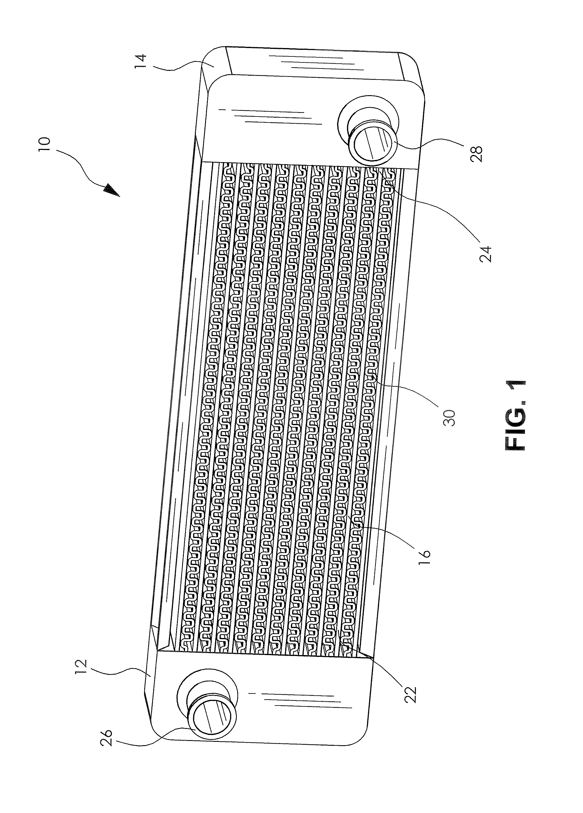
[0019]FIG. 1 shows a heat exchanger assembly 10 according to an embodiment of the invention. The heat exchanger assembly 10 includes a first header 12 and a second header 14 disposed on opposing ends thereof. In the embodiment shown, the heat exchanger assembly 10 is a parallel flow type heat exchanger assembly commonly referred to as a radiator. However, it should be understood that other types of heat exchanger assemblies can be used such as a serpentine-flow type heat exchanger assembly and a U-flow type heat exchanger assembly, for example.

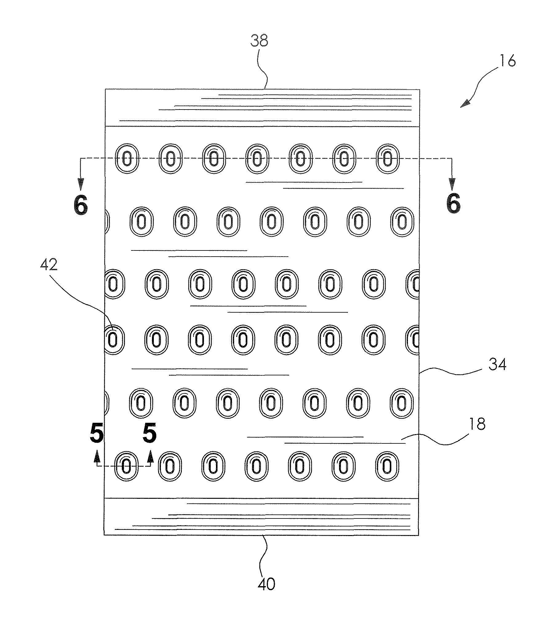
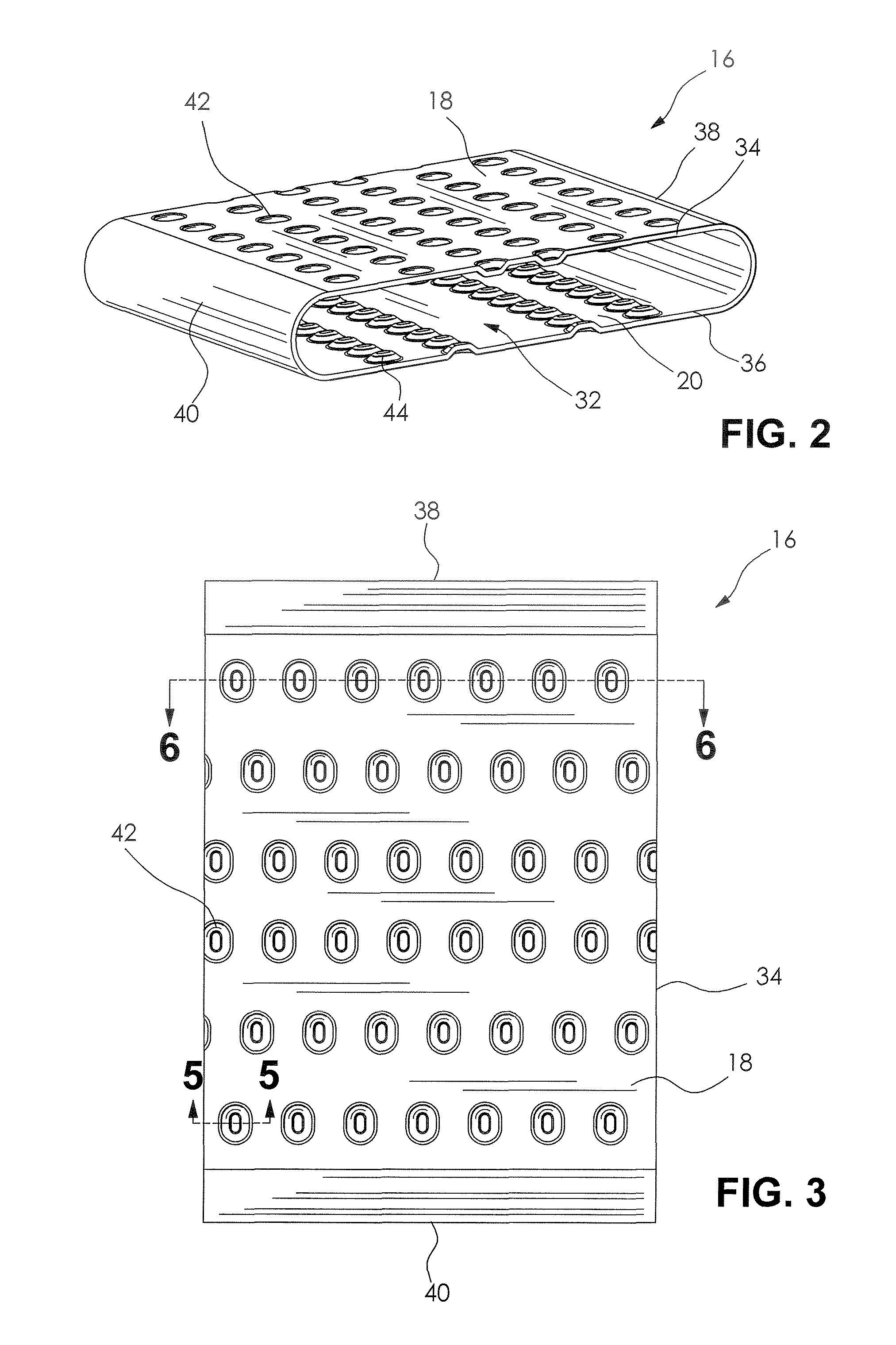
[0020]The heat exchanger assembly 10 also includes a plurality of spaced apart substantially parallel tubes 16. As more clearly illustrated in...


PUM


Abstract

A tube for a heat exchanger is disclosed, the tube including a plurality of protuberances formed on an inner surface of the tube. The protuberances are arranged in a pattern that maintains a substantially constant cross sectional hydraulic area along a length of the tube.

Description

FIELD OF THE INVENTION[0001]The invention relates generally to a tube for use in a heat exchanger, and more particularly to a tube including a plurality of deformations formed on a surface thereof for use in a heat exchanger.BACKGROUND OF THE INVENTION[0002]Heat exchangers are used for changing a temperature of various working fluids such as an engine coolant, an engine lubricating oil, an air conditioning refrigerant, and an automatic transmission fluid, for example. The heat exchanger typically includes a plurality of spaced apart fluid conduits or tubes connected between an inlet tank and an outlet tank, and a fin disposed between adjacent conduits. Air is directed across the fins of the heat exchanger by a cooling fan or a motion of a vehicle, for example. As the air flows across the fins, heat in a fluid flowing through the tubes is conducted through the walls of the tubes, into the fins, and into the air.[0003]One of the primary goals in heat exchanger design is to achieve the...

Claims


Application Information

Patent Timeline
Patent Type & Authority Patents(United States)
IPC IPC(8): F28F1/42
CPCF28D1/05366F28F1/40F28F3/044
Inventor STEWART, GRAEME
Owner HANON SYST
Why Eureka
Try Eureka