Wireless communication device, wireless communication system, wireless communication method and program

a wireless communication and wireless communication technology, applied in multiplex communication, orthogonal multiplex, polarisation/directional diversity, etc., can solve the problem of inability to increase the transmission bandwidth from the transmission source device to the receiving destination device, and achieve the effect of increasing the transmission bandwidth of the wireless communication device and preventing errors from occurring again

Inactive Publication Date: 2012-09-18
SONY CORP
View PDF18 Cites 7 Cited by
  • Summary
  • Abstract
  • Description
  • Claims
  • Application Information

AI Technical Summary

Benefits of technology

[0011]With this configuration, the first transmission portion and the second transmission portion transmit radio signals in parallel. Accordingly, the wireless communication device can obtain a larger transmission band than in the case of transmitting radio signals only from one transmission portion. Further, the adjustment portion adjusts the start timing of the second frequency hopping pattern used by the second transmission portion such that the time slot of each of the frequency bands used by the first transmission portion and the time slot of each of the frequency bands used by the second transmission portion are not the same. Accordingly, it is possible to suppress interference between the radio signal transmitted from the first transmission portion and the radio signal transmitted from the second transmission portion. In summary, the wireless communication device can increase the transmission bandwidth while suppressing interference between two types of radio signals.
[0012]The first transmission portion may start transmission of a radio signal in accordance with the first frequency hopping pattern after transmitting a first preamble, and the second transmission portion may start transmission of a radio signal in accordance with the second frequency hopping pattern after transmitting a second preamble. The adjustment portion may perform adjustment such that the transmission of the second preamble from the second transmission portion is started after completion of the transmission of the first preamble from the first transmission portion. With this configuration, the first preamble and the second preamble are transmitted in different time slots. Thus, interference between the first preamble and the second preamble can be inhibited. Accordingly, synchronization with the first preamble and with the second preamble can be more reliably achieved at a receiving destination device.
[0014]The wireless communication device may further include: a first beacon generation portion that generates a beacon including information that inhibits transmission of a radio signal in the second beacon period; and a second beacon generation portion that generates a beacon including information that inhibits transmission of a radio signal in the first beacon period. Further, the first transmission portion may transmit the beacon generated by the first beacon generation portion, and the second transmission portion may transmit the beacon generated by the second beacon generation portion. With this configuration, transmission of a radio signal in the second beacon period from a wireless communication device included in the first wireless network is inhibited based on the beacon transmitted from the first transmission portion. Thus, the second beacon period of the second wireless network can be protected. Further, transmission of a radio signal in the first beacon period from a wireless communication device included in the second wireless network is inhibited based on the beacon transmitted from the second transmission portion. Thus, the first beacon period of the first wireless network can be protected.
[0016]The wireless communication device may further include: a transmission buffer that temporarily stores transmission data to be transmitted from the first transmission portion as a radio signal; and a determination portion that causes also the second transmission portion to transmit a radio signal when a data amount of the transmission data stored in the transmission buffer exceeds a predetermined value. Further, the determination portion may stop the transmission of a radio signal from the second transmission portion when the data amount of the transmission data stored in the transmission buffer becomes equal to or less than the predetermined value. With this configuration, when the data amount of the transmission data stored in the transmission buffer exceeds the predetermined value, the transmission bandwidth of the wireless communication device is increased. Accordingly, even when the data amount of the transmission data stored in the transmission buffer exceeds the predetermined value, the transmission data can be transmitted rapidly.
[0017]The wireless communication device may further include an allocation portion that allocates the transmission data stored in the transmission buffer to the first transmission portion and the second transmission portion. When the transmission data transmitted as a radio signal from one of the first transmission portion and the second transmission portion is not received properly by a receiving destination device, the allocation portion may allocate the transmission data to the other transmission portion for retransmission. With this configuration, the transmission data that has not been transmitted successfully is retransmitted using a different method. Thus, it is possible to prevent errors occurring again when transmitting the transmission data.
[0023]According to the embodiments of the present invention described above, transmission bandwidth can be increased in one direction.

Problems solved by technology

However, the transmission bandwidth from the transmission source device to the receiving destination device cannot be increased.

Method used


Image

  • Wireless communication device, wireless communication system, wireless communication method and program
  • Wireless communication device, wireless communication system, wireless communication method and program
  • Wireless communication device, wireless communication system, wireless communication method and program

Examples


Embodiment Construction

[0063]Hereinafter, preferred embodiments of the present invention will be described in detail with reference to the appended drawings. Note that, in this specification and the appended drawings, structural elements that have substantially the same function and structure are denoted with the same reference numerals, and repeated explanation of these structural elements is omitted.

[0064]The preferred embodiment for practicing the present invention will be described in the order shown below.

[0065]1. Overview of wireless communication system according to the present embodiment

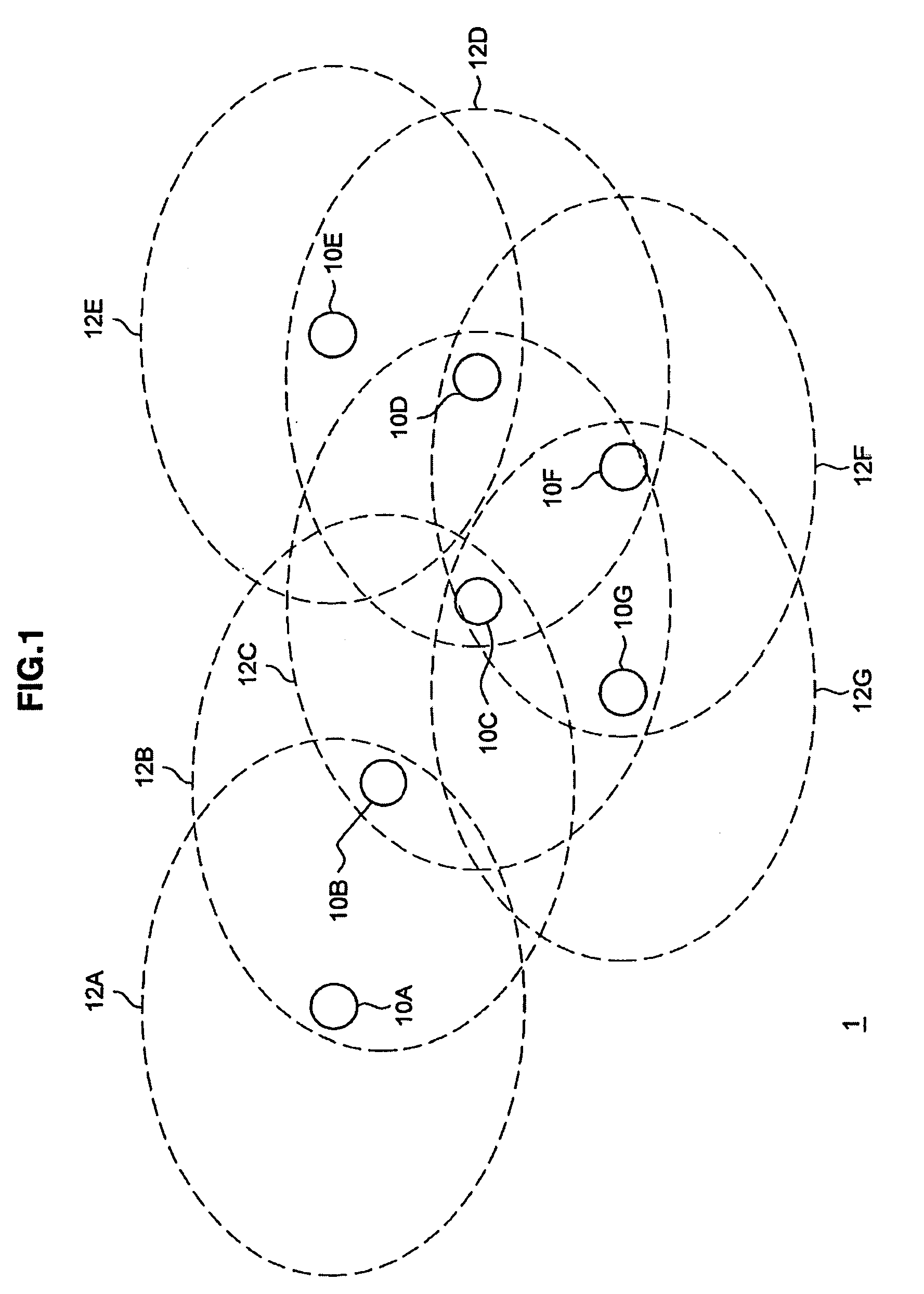
[0066]1-1. Example of the configuration of the wireless communication system

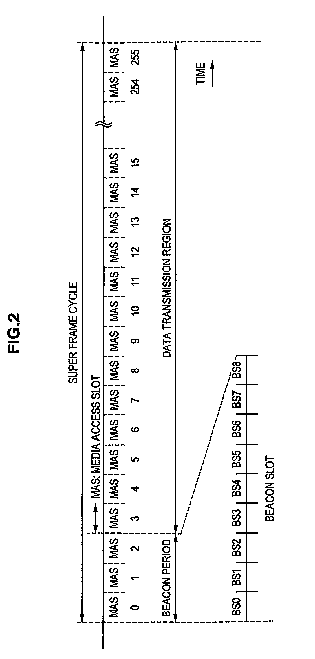
[0067]1-2. Time sharing control

[0068]1-3. TFC code

[0069]2. Background of the present embodiment

[0070]3. Detailed description of the present embodiment

[0071]3-1. Outline of wireless communication according to the present embodiment

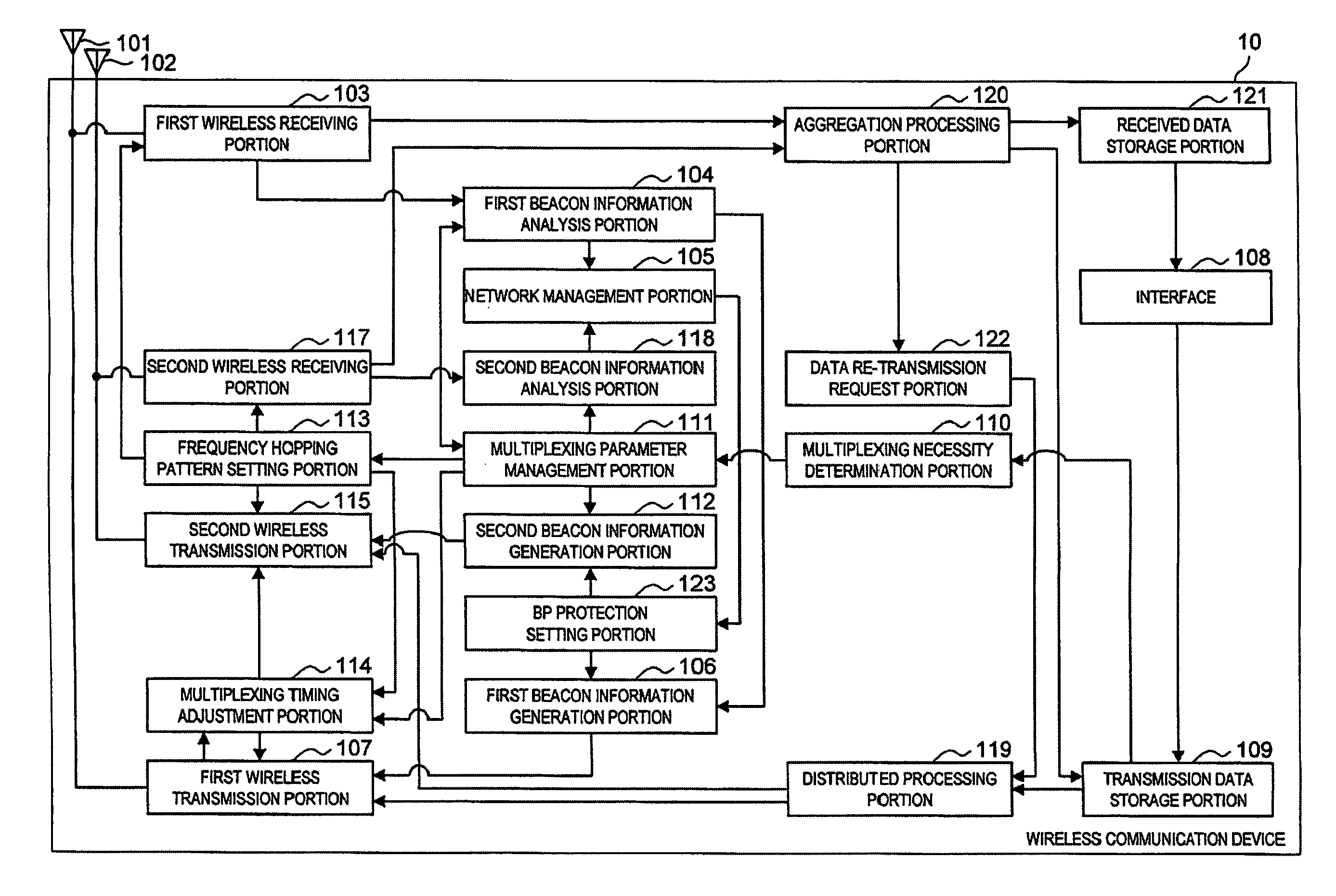
[0072]3-2. Configuration of wireless communication device according to the present embodiment

[0073]3-3. Operatio...


PUM


Abstract

A wireless communication device includes: a first transmission portion that transmits a radio signal using a plurality of frequency bands in accordance with a first frequency hopping pattern; a second transmission portion that transmits a radio signal using a plurality of frequency bands in accordance with a second frequency hopping pattern that differs from the first frequency hopping pattern; and an adjustment portion that adjusts a start timing of the second frequency hopping pattern such that a time slot of each of the plurality of frequency bands used by the first transmission portion and a time slot of each of the plurality of frequency bands used by the second transmission portion are not the same.

Description

CROSS REFERENCES TO RELATED APPLICATIONS[0001]The present invention contains subject matter related to Japanese Patent Application JP 2008-055256 filed in the Japan Patent Office on Mar. 5, 2008, the entire contents of which being incorporated herein by reference.BACKGROUND OF THE INVENTION[0002]1. Field of the Invention[0003]The present invention relates to a wireless communication device, a wireless communication system, a wireless communication method, and a program.[0004]2. Description of the Related Art[0005]In a known multi band orthogonal frequency division multiplexing (OFDM) system, a wireless communication method is defined in which a plurality of frequency bands are sequentially used according to a certain frequency hopping pattern.[0006]Further, a plurality of frequency hopping patterns are defined in the multi band OFDM system. It has been suggested that a plurality of wireless communication devices can coexist by using different frequency hopping patterns selected from...

Claims


Application Information

Patent Timeline
Patent Type & Authority Patents(United States)
IPC IPC(8): H04B1/00H04B1/713H04B1/7156H04J11/00
CPCH04L5/0007H04L5/003H04L5/0037
Inventor SUGAYA, SHIGERU
Owner SONY CORP
Why Eureka
Try Eureka