
Optical moisture sensor

a moisture sensor and optical technology, applied in the direction of instruments, generating/distributing signals, discharge tubes/lamp details, etc., can solve the problems of self-closing skylights and windows, relatively rare, and condensation sensing in heating, cooling and ventilation systems is rarely don

Active Publication Date: 2012-09-18
HYDREON CORP
View PDF18 Cites 14 Cited by
  • Summary
  • Abstract
  • Description
  • Claims
  • Application Information

AI Technical Summary

Benefits of technology

The sensor offers enhanced sensitivity to both high and low humidity and precipitation events, is cost-effective, and maintains accuracy in harsh environments, including desert conditions and HVAC systems, with self-cleaning properties and efficient condensation detection.

Problems solved by technology

For example, self-closing skylights and windows exist, but are relatively rare because of the lack of sufficiently sensitive moisture sensors.
Condensation sensing in heating, cooling and ventilation systems is rarely done, because no currently available sensor is sufficiently reliable.
Accurate recording of moisture in desert environments does not occur because available sensor systems are not sufficiently sensitive.

Method used


Image

  • Optical moisture sensor
  • Optical moisture sensor
  • Optical moisture sensor

Examples


Embodiment Construction

[0022]The present invention relates to a self-contained optical moisture sensor suitable for a wide variety of non-vehicular applications.

[0023]It is to be understood that the invention may assume various alternative orientations and step sequences, except where expressly specified to the contrary. It is also to be understood that the specific devices and processes illustrated in the attached drawings, and described in the following specification are simply exemplary embodiments of the inventive concepts defined in the appended claims. Hence, specific dimensions, directions or other physical characteristics relating to the embodiments disclosed are not to be considered as limiting, unless the claims expressly state otherwise.

[0024]While automotive optical rain sensors are well adapted for the purpose of, for example, windshield wiper control, they generally must be rigidly affixed to glass or some other substrate material and housed in a watertight container. Thus, they are not dire...


PUM


Abstract

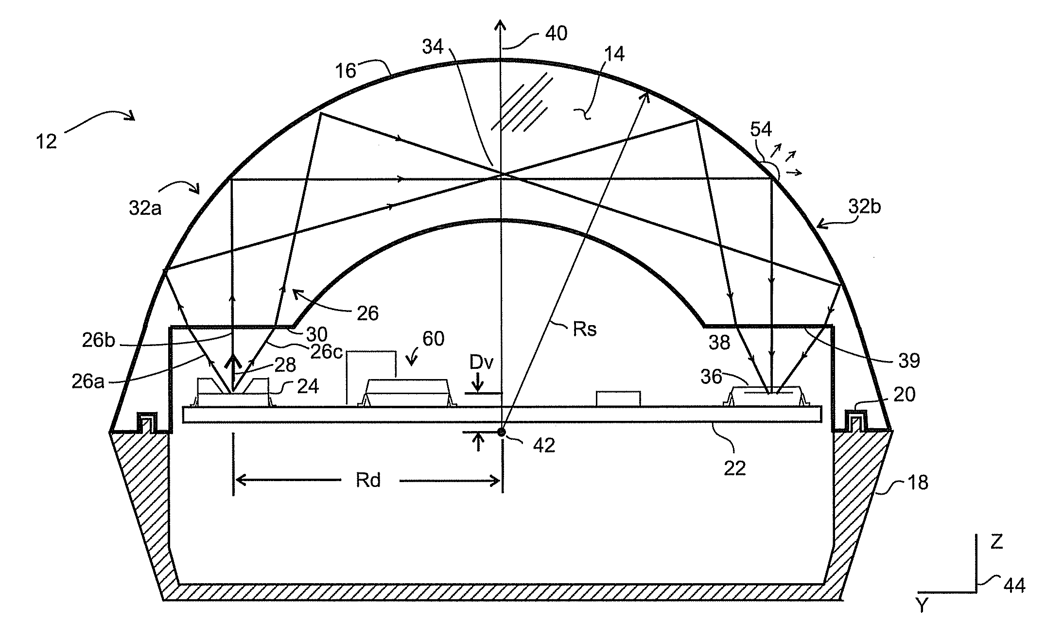
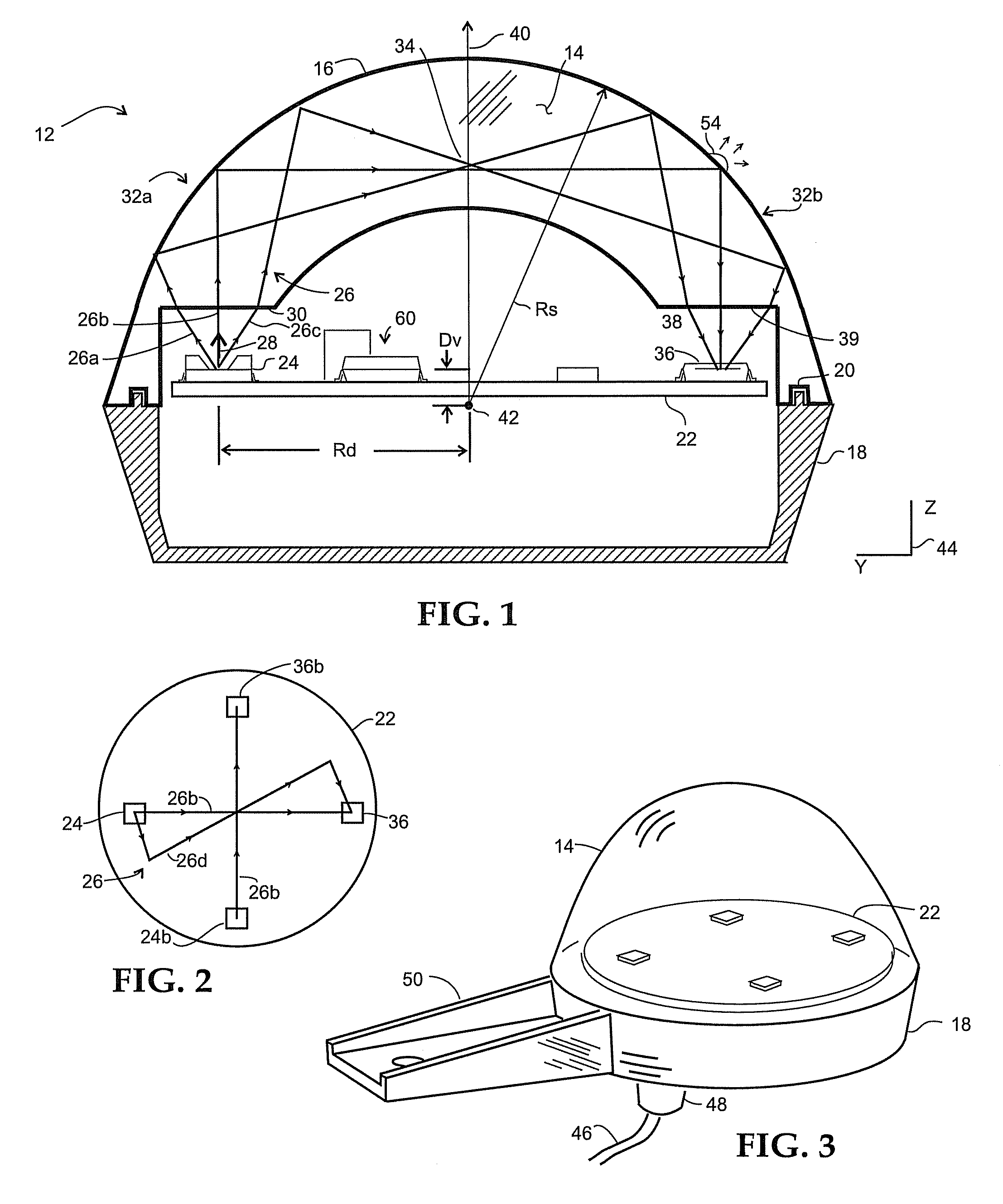
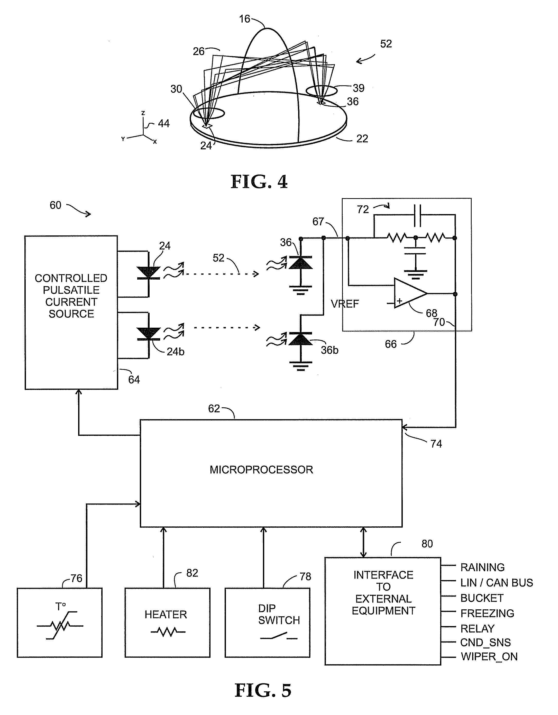
A moisture sensor is provided that simultaneously achieves ruggedness, sensitivity, wide dynamic range, versatility of application, and low cost. The outer, top service of the sensor is a lens having a predetermined geometric shape which preferably makes the rain sensor resistant to the build up of debris on the outer surface as well as being effectively self-cleaning. Within a housing of the rain sensor, at least one light emitter and at least one light detector are each deployed on a substantially planar circuit board facing such outer lens surface. So arranged, light rays from the at least one emitter strike the outer lens surface and is reflected about 90°, whereupon it strikes the outer lens surface once more and is again reflected therefrom about 90° to focus back onto the at least one detector. Raindrops present on the outside surface of the sensor affect the intensity of the light rays reflected and signals from the at least one light detector are sent to control circuitry within the rain sensor. A microprocessor in the sensor processes the resulting data to detect rain intensity over a wide range so as to be capable of being effectively deployed for applications such as to emulate a tipping bucket style rain detector, providing condensation sensing, and automatically adjusting the strength of the light rays emitted by the at least one light emitter to provide improved consistency of operation of the sensor over time.

Description

RELATED APPLICATION[0001]This application is claiming the benefit, under 35 U.S.C. 119(e), of the provisional application filed Aug. 28, 2009 under 35 U.S.C. 111(b), which was granted Ser. No. 61 / 237,715. This provisional application is hereby incorporated by reference in its entirety.BACKGROUND[0002]The present invention relates to an optical moisture sensor. More particularly, the present invention relates to a self-contained optical moisture sensor suitable for a wide variety of non-vehicular applications.[0003]Rain sensors for use in vehicular applications are well known. Rain and moisture sensors for various non-vehicular applications are also known in the patent literature, for example:[0004]U.S. Pat. No. 3,705,533 describes a precipitation sensor having two buckets secured to each other for tilting movement between two end positions, is provided with a precipitation collecting and distributing means which collects precipitation during tilting of the buckets and has a normally...

Claims


Application Information

Patent Timeline
Patent Type & Authority Patents(United States)
IPC IPC(8): G06F1/14
CPCG01N21/552G01W1/14
Inventor TEDER, REIN S.
Owner HYDREON CORP
Learn More