
System and method for faucet installations

Active Publication Date: 2012-09-25
LISTON THOMAS D
View PDF26 Cites 23 Cited by
  • Summary
  • Abstract
  • Description
  • Claims
  • Application Information

AI Technical Summary

Benefits of technology

[0010]A retention nut, the retention nut including a pair of sections, each section having a concave inner surface and an outer surface, each of the inner surfaces having an engagement protrusion that has been adapted for engaging the engagement recesses in the external surface of the valve stem, the sections of the retention nut being adapted for connecting to one another, so that when the retention nut sections are connected to one another they provide support for biasing the engagement protrusion towards the external surface of the valve stem, and thus allow the engagement protrusion into the engagement recesses.
[0013]While it is contemplated that the disclosed system may be used with standard valve sets that require the attachment of a water supply line between the supply valve and the valve stems, it is also contemplated that the disclosed system will allow the fabrication of valve sets that have water supply hoses pre-connected by the manufacturer. This arrangement would eliminate, or greatly reduce, the possibility of leakage at the connection between the water supply line and the valve stem, and would provide the benefits of the simplified installation method disclosed here.

Problems solved by technology

The problem associated with faucet systems that use a pair of faucet bodies, each with its own valve assembly, is that they first require insertion of the threaded valve stem into the sink or counter top holes, then require the mounting of the wing nuts, and then the installation of the water supply line to the end of the valve stem.
This process is rather tedious, and often very frustrating due to the fact that the installer must often lie on his back while installing these components.
The installer's position makes it difficult to properly align the components often results in damage to the threaded sections, further complicating the proper installation.
To make matters worse, the valve stem is often made of metal, and the nut or threaded connector of the supply line is often made of a plastic, which again increases the possibility of thread damage during attempts at installing the faucet.
However, the use of these fittings is typically limited to low-pressure installations of a supply or drainage line to the end of a fitting.

Method used


Image

  • System and method for faucet installations
  • System and method for faucet installations
  • System and method for faucet installations

Examples


Embodiment Construction

[0024]While the invention will be described and disclosed here in connection with certain preferred embodiments, the description is not intended to limit the invention to the specific embodiments shown and described here, but rather the invention is intended to cover all alternative embodiments and modifications that fall within the spirit and scope of the invention as defined by the claims included herein as well as any equivalents of the disclosed and claimed invention.

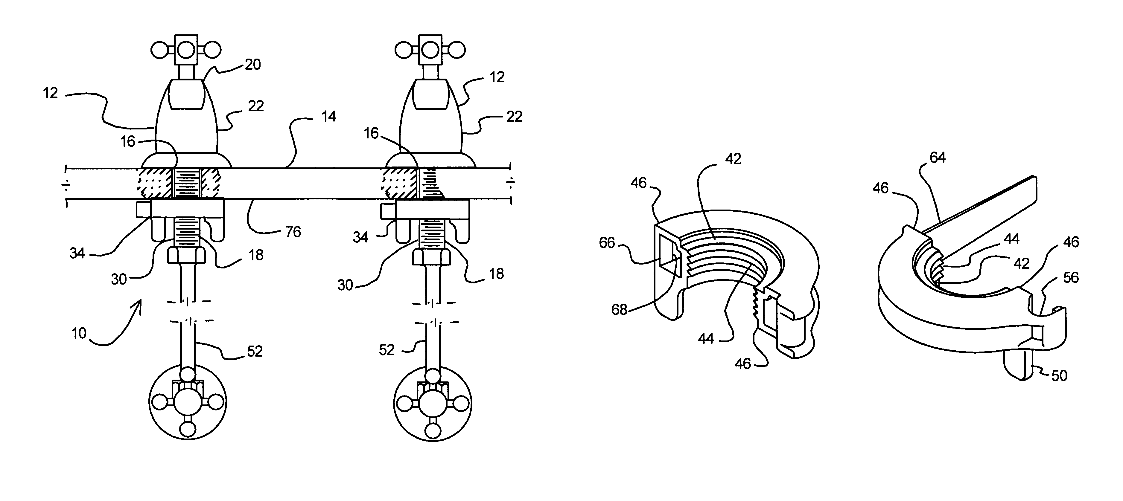
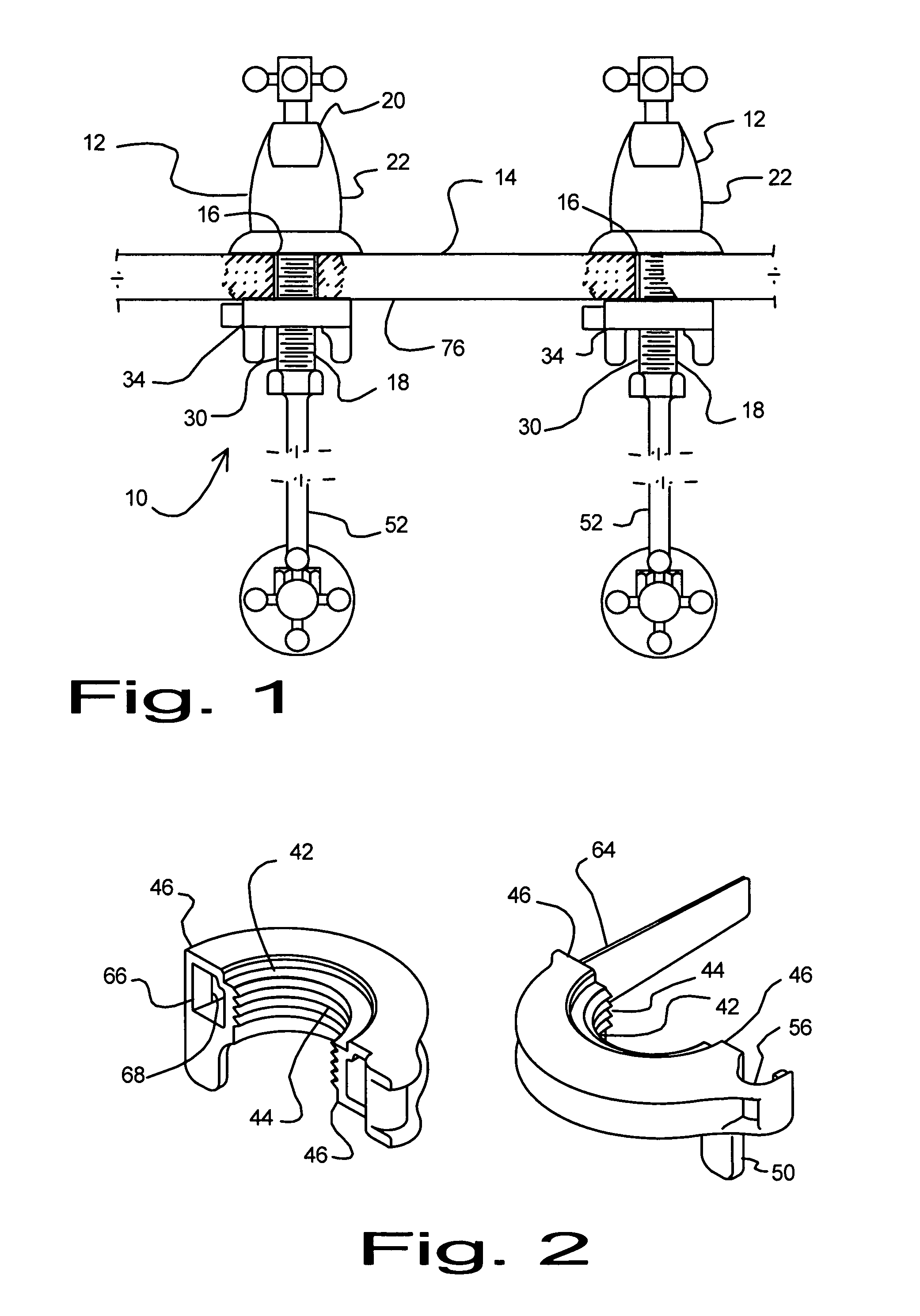
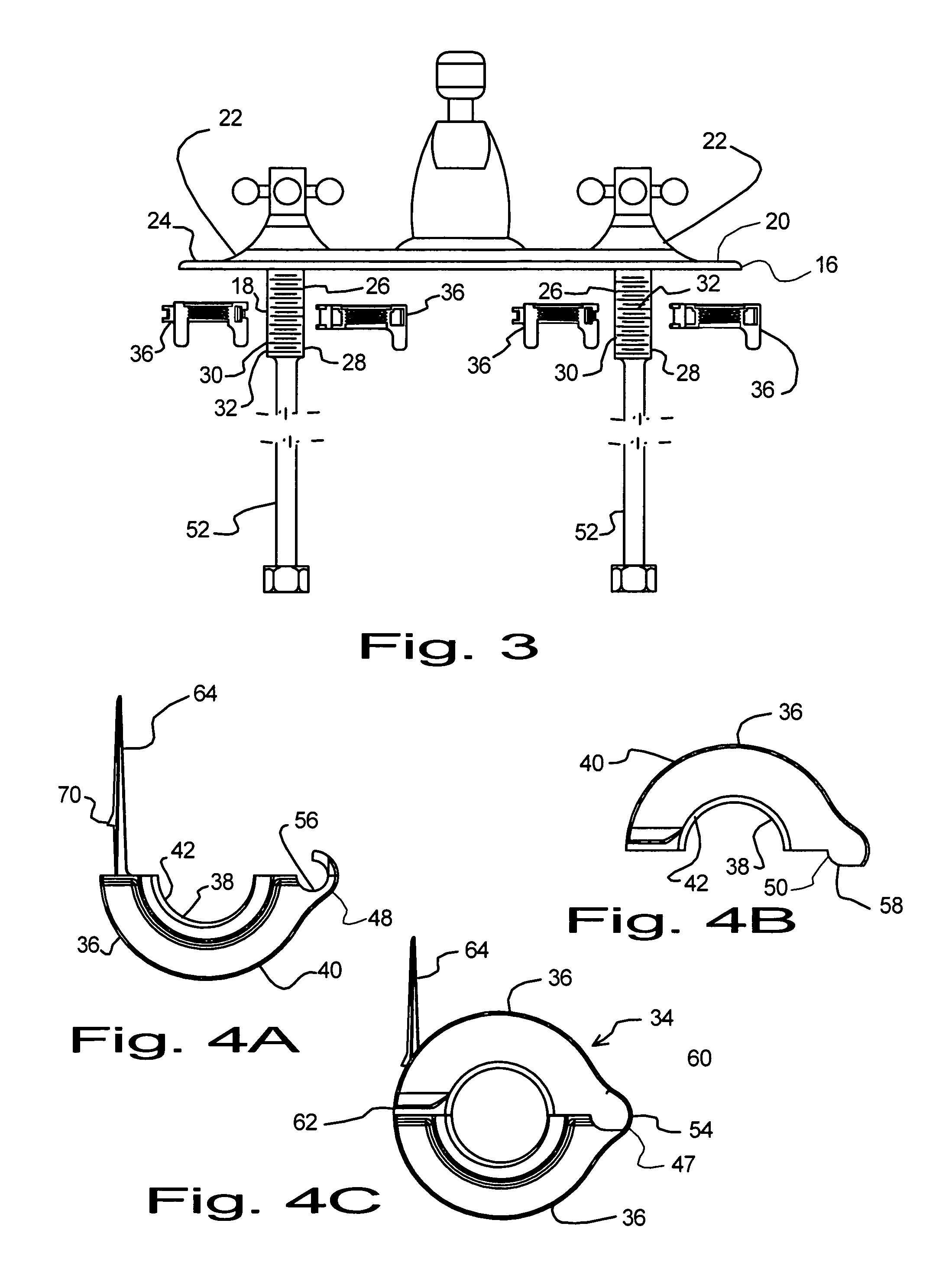
[0025]Turning now to FIG. 1 where a faucet installation system 10 for installing a faucet valve 12 on a sink or countertop 14 has been illustrated. It will be understood from FIG. 1 that the sink or countertop will include at least one and preferably a pair of mounting apertures 16 adapted for accepting the valve stem 18 of the faucet 20 that is to be mounted. It is contemplated that the disclosed invention will be particularly useful for valve assemblies 22 that include a pair of faucet valves 12 connected to one a...


PUM


Abstract

A faucet installation system and method for use on faucets that include a valve stem that is adapted for insertion through an aperture in a sink or a countertop is disclosed. The system uses a valve having a valve stem that is adapted for connection to a water supply line that connects to a water supply valve. The valve stem includes an external surface that cooperates with a retention nut that is split, so that retention nut may be attached to the valve stem after the valve stem and water supply line have been attached to one another and inserted through the aperture in the sink or countertop, eliminating the need to attach the water supply line to the stem from under the sink or countertop.

Description

BACKGROUND OF THE INVENTION[0001](a) Field of the Invention[0002]This application relates to a system and method for installing and fastening faucets onto surfaces. More particularly, but not by way of limitation, to a system and method that uses a split-nut for engaging the valve stems and tightening the valve stems against the surface that supports the faucet.[0003](b) Discussion of Known Art[0004]Common faucet systems used in household applications include a hot water valve assembly and a cold water valve assembly. An example of this type of faucet systems is disclosed in U.S. Pat. No. 5,946,746, incorporated herein in its entirety by reference. These types of faucet systems include a pair of valves, each with a valve body that includes a threaded valve stem, to which a water supply line is attached. The threaded valve stem is also used to accept wing nuts that are used to retain the valve body against the sink or the counter top to which the sink or faucet system is mounted.[000...

Claims


Application Information

Patent Timeline
IPC IPC(8): E03C1/00
CPCE03C1/0401Y10T137/87684
Inventor LISTON, THOMAS D.CONRAD, ZACHARY E.
Owner LISTON THOMAS D
Features
  • Generate Ideas
  • Intellectual Property
  • Life Sciences
  • Materials
  • Tech Scout
  • Unparalleled Data Quality
  • Higher Quality Content
  • 60% Fewer Hallucinations
Learn More