Piston-chamber combination

a technology of piston chamber and piston shaft, which is applied in the direction of vibration dampers, engines without rotary main shafts, and shafts, etc., to achieve the effect of preventing translation in the longitudinal direction of the combination relative to the base and substantial deflection angles of the chamber

Inactive Publication Date: 2012-09-25
NVB INT UK
View PDF9 Cites 4 Cited by
  • Summary
  • Abstract
  • Description
  • Claims
  • Application Information

AI Technical Summary

Benefits of technology

[0010]Force providers for enabling the relative movement of the parts of the combination may move themselves, and the path of the last mentioned movement does not at any time comply exactly with the path of the relative movement of the piston rod, the piston and the chamber. Thus the system of the force provider and the combination may provide a flexibility somewhere in the system in order to avoid damage. When the force provider may engaging the combination with changing forces, and which may also keeping the non-moving part of the combination towards a rigid surface, in order to enable said relative movement, there may be conflicting demands towards the combination, if said rigid surface also has the function of providing reaction forces for the combination. The last mentioned may happen when a pump is engaged by a human body, while the pump is being held down to the rigid surface e.g. a floor, by a foot of said user. Specifically when a standing person is using a floor pump for pumping a tyre, and specifically if the floor is not in level. The combination ought therefore be movable in relation to the rigid surface, in order to follow the path of the force provider.
[0017]In a sixth aspect, the combination may be joined together with the basis by means of an elastically deformable bushing. The bushing is mounted in a hole of the basis, and the chamber is mounted in the hole of the bushing, or vice versa. With appropriate fittings, the combination may be assembled in the basis without being able to move in the longitudinal direction. The combination may at least now rotate in the bushing relative to the basis, and thus relative to the rigid surface. The deflection of the combination is deforming the flexible wall of the bushing. The wall thickness of the bushing may be much bigger than the wall thickness of the chamber, enabling substantial deflection angles of the chamber.
[0018]Moreover, it might be possible that the fitting is of such a character, that it may also hold the forces of the combination in relation to the basis during the stroke, incl. the ends of the stroke, so that a translation in the longitudinal direction of the combination relative to the basis is prevented.
[0019]In a seventh aspect, an improved bushing may have a protrusion on its top, which is connected to the top of the basis. This prevents the bushing to move in a direction towards the basis. By adding another protrusion on the inside of the bushing or at the outside of the combination, combined with a groove the combination and bushing, respectively a possible translation of the combination to and from the basis may be prevented.
[0030]In the case of classic floor pumps, with cylinders with circular cross sections of constant size, high working forces may occur. If relatively high forces are to be transferred from the arm of the user through the hand, connected to this arm, the hand will be best positioned in relation to the arm, when no force moments would arise. This is obtained if the longitudinal axis of the arm goes through the center point of the axis of a portion of the handle, the handle gripped by the hand, connected to the arm.

Problems solved by technology

Force providers for enabling the relative movement of the parts of the combination may move themselves, and the path of the last mentioned movement does not at any time comply exactly with the path of the relative movement of the piston rod, the piston and the chamber.

Method used


Image

  • Piston-chamber combination
  • Piston-chamber combination
  • Piston-chamber combination

Examples


Embodiment Construction

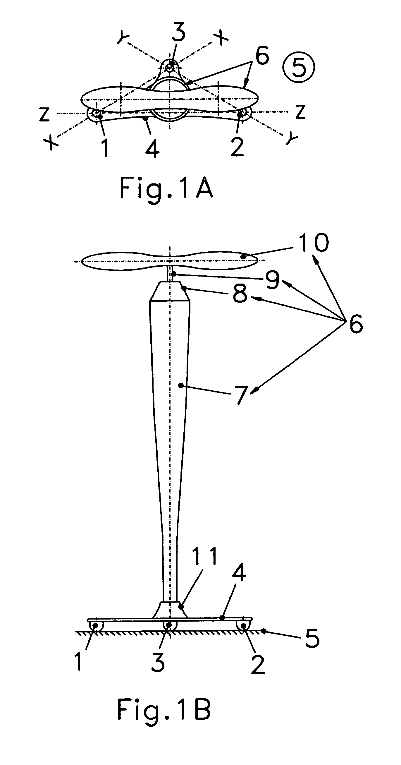
[0085]FIG. 1A shows line XX between two of the three engaging surfaces 1,2 of the basis 4 with a rigid surface 5, around which the combination 6 may move. The line Y-Y between two of the three engaging surfaces 2,3 of the basis 4 with a rigid surface 5, around which the combination 6 may move. The line Z-Z between two of the three contact points 1,2 of the basis 4 with a rigid surface 5, around which the combination 6 may move.

[0086]FIG. 1B shows the combination 6, comprising a chamber 7, a guiding 8 for the piston rod 9, a handle 10. The basis 4 with contact points 1, 2 and 3, which are rounded off towards the rigid surface. The chamber 7 is rigidly connected to the basis 4 by means of reinforcement 11.

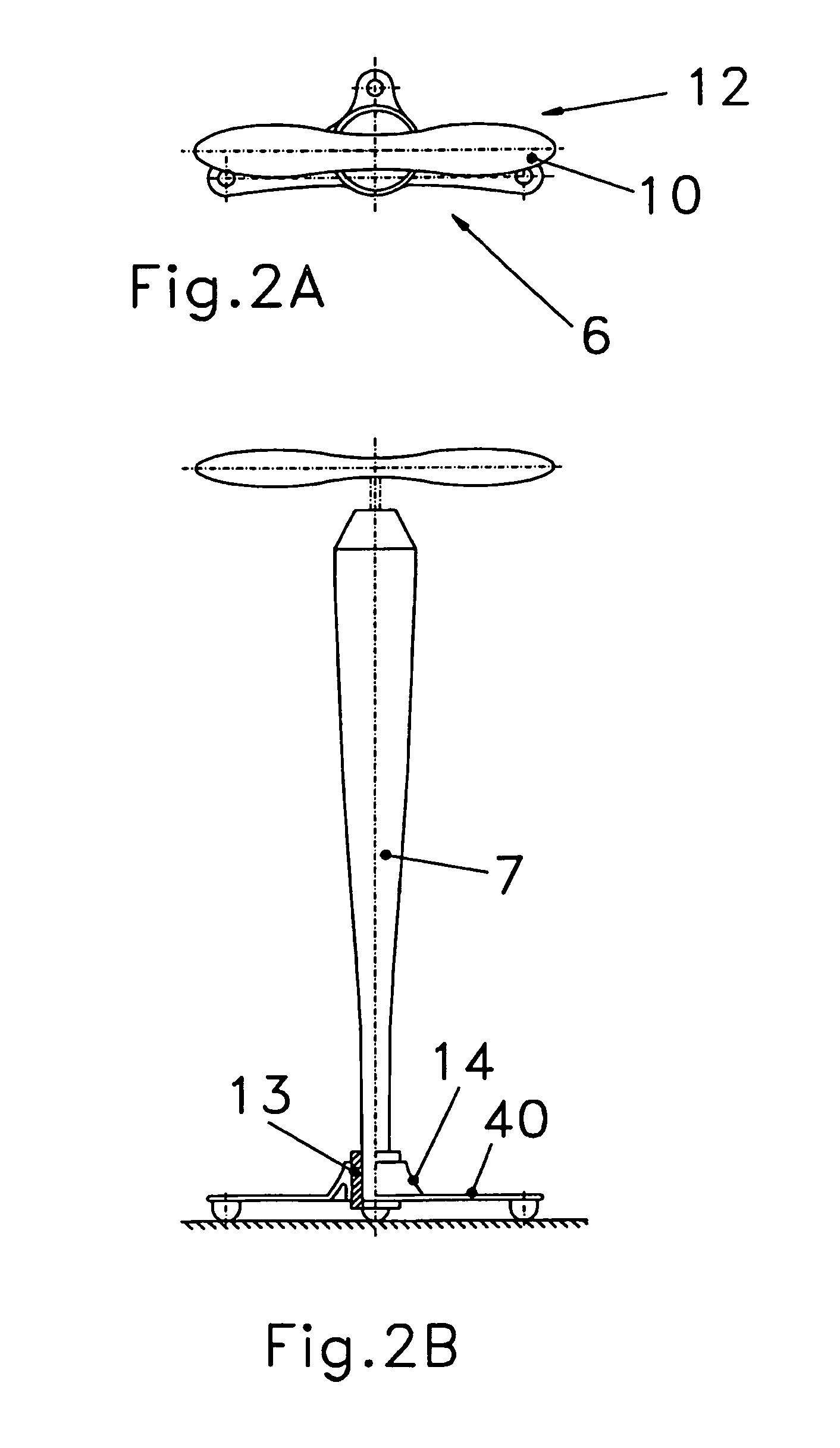
[0087]FIG. 2A shows the handle 10 of the combination 6 when the combination 6 is in its rest position 12.

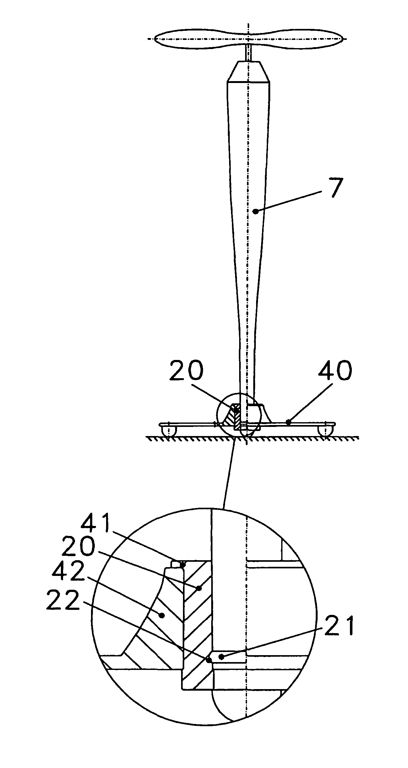
[0088]FIG. 2B shows the combination 6 in its rest position 12, when the transition 13 between the combination 6 and the reinforcement 14 of the basis 40 is in its rest position. T...


PUM


Abstract

A piston-chamber combination comprising an elongate chamber which is bounded by an inner chamber wall, and comprising a piston means in said chamber to be sealingly movable relative to said chamber wall at least between a first and a second longitudinal position of the chamber, said chamber having cross-sections of different cross-sectional areas at the first and second longitudinal positions, and at least substantially continuously differing cross-sectional areas at intermediate longitudinal positions between the first and second longitudinal positions, the cross-sectional area at said second longitudinal position being smaller than the cross-sectional area at said first longitudinal position, said piston means can change dimensions thereby providing for different cross-sectional areas of the piston means adapting the same to said different cross-sectional areas of the chamber during the relative movements of the piston means between the first and second longitudinal positions through said intermediate longitudinal positions of the chamber, said combination engaging a rigid surface. Said combination is movable relative to said surface.

Description

TECHNICAL FIELD[0001]A piston-chamber combination comprising an elongate chamber which is bounded by a inner chamber wall, and comprising a piston in said chamber to be sealingly movable relative to said chamber wall at least between a first longitudinal position and a second longitudinal positions of the chamber, said combination engaging a rigid surface.BACKGROUND OF THE INVENTION[0002]This invention deals with solutions for avoiding damaging the combination, as the piston rod and / or the chamber may use a path during the stroke which is not the line or curve of the movement of the force provider, or force receiver, respectively, the last mentioned provider / receiver engaging the piston rod / chamber.[0003]In specifically Dutch prior art of the beginning of the last century, a number of flexible transitions between the basis e.g. a foot plate and the bottom of the cylinder can be observed for classic bicycle floor pumps: a piece of rubber, enabling the cylinder to move in a cone shape...

Claims


Application Information

Patent Timeline
Patent Type & Authority Patents(United States)
IPC IPC(8): F04B33/00F16F9/00
CPCF04B33/005F04B33/00F15B15/00F16F9/00
Inventor VAN DER BLOM, NICOLAAS
Owner NVB INT UK
Why Eureka
Try Eureka