Cleaning device and methods

a cleaning device and cleaning method technology, applied in the field of tissue removal, can solve the problems that previously treated tissue in the ablation field can impair subsequent ablation of the same area

Active Publication Date: 2012-09-25
TYCO HEALTHCARE GRP LP
View PDF484 Cites 36 Cited by
  • Summary
  • Abstract
  • Description
  • Claims
  • Application Information

AI Technical Summary

Problems solved by technology

During ablation procedures to treat various disease states, previously treated tissue in the ablation field can impair subsequent ablation of the same area if the treated tissue remains adherent to the ablation zone.

Method used


Image

  • Cleaning device and methods
  • Cleaning device and methods
  • Cleaning device and methods

Examples


Embodiment Construction

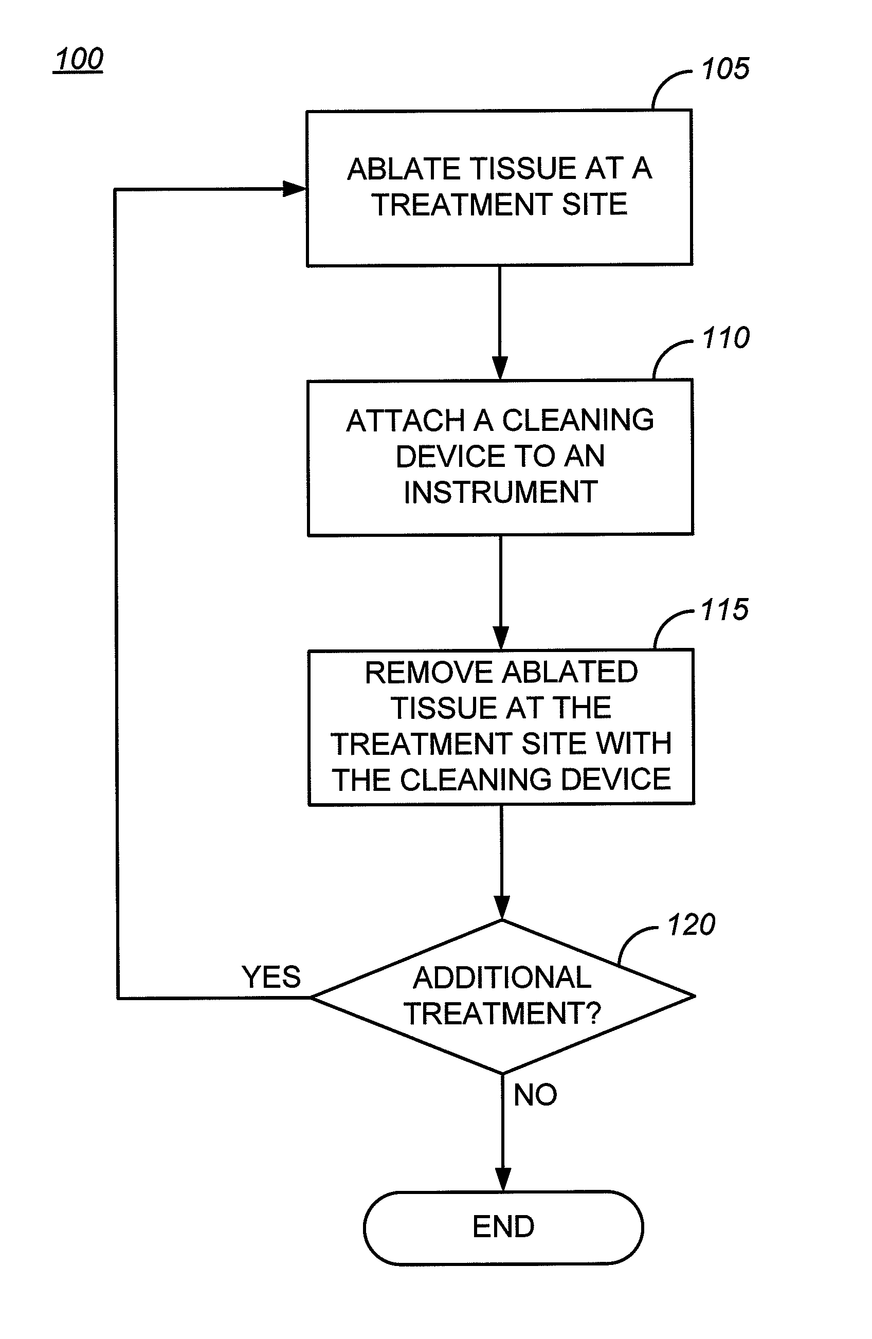
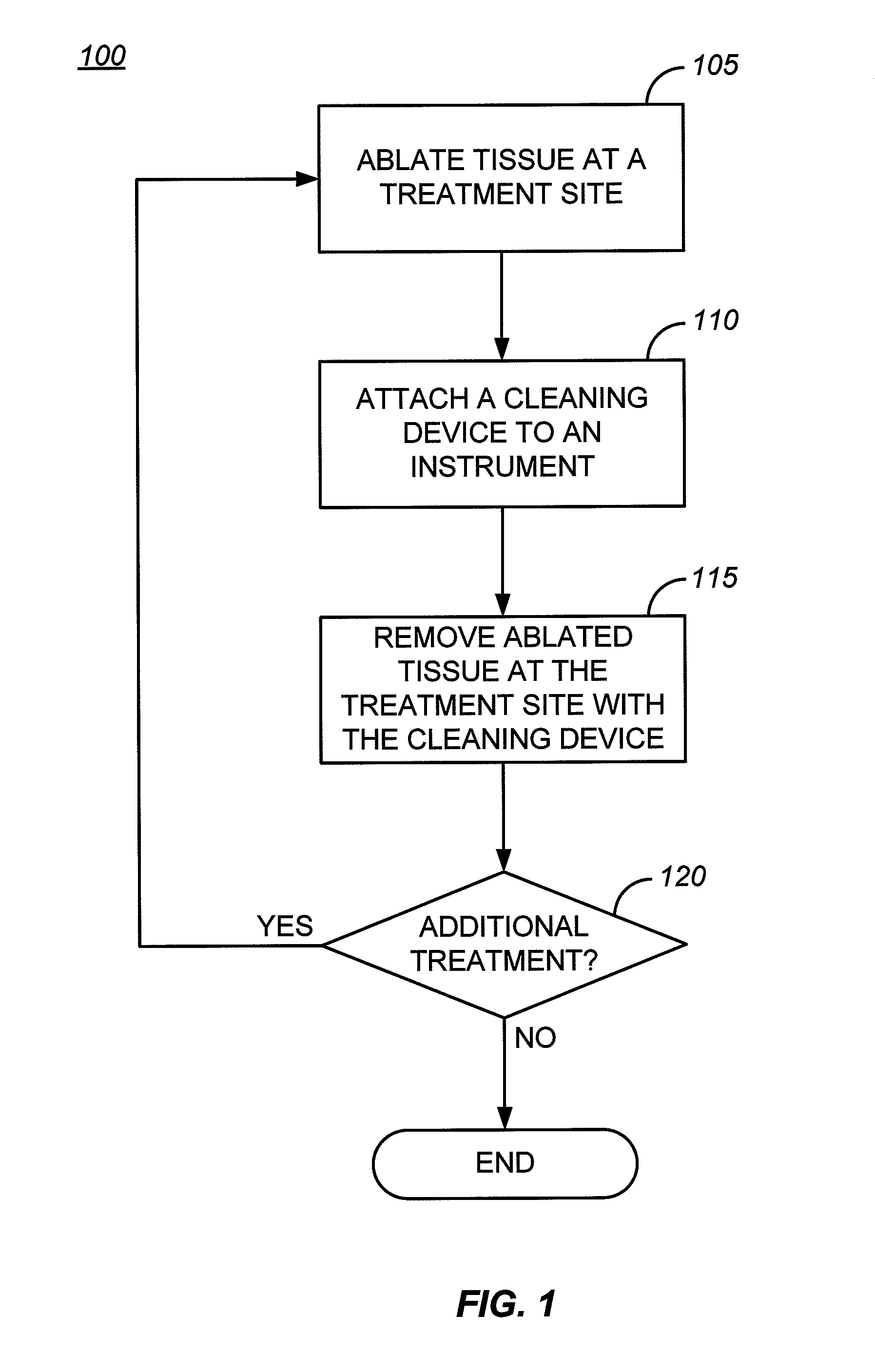
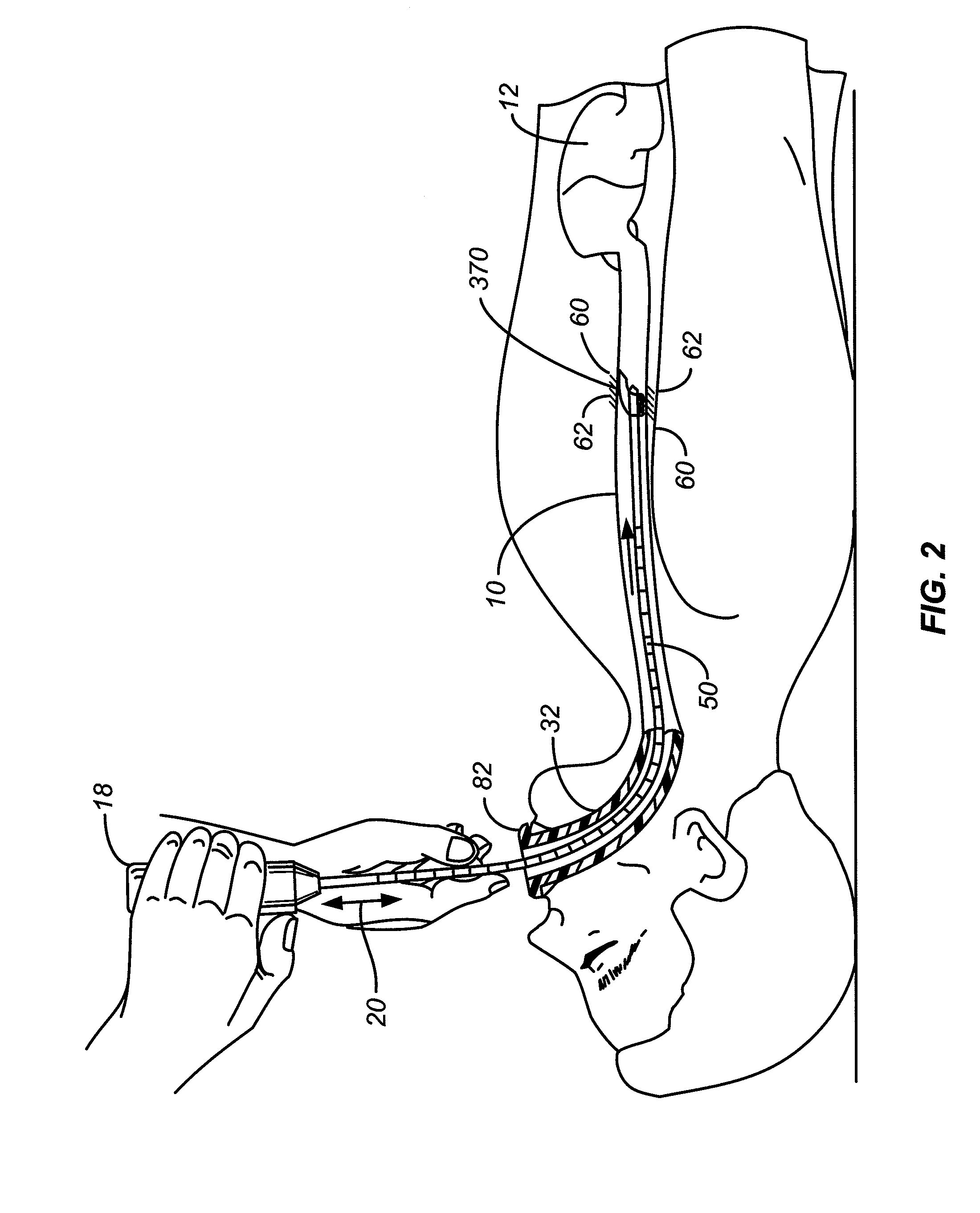
[0040]FIG. 1 is a flowchart 100 illustrating one embodiment of method of the invention. First, at step 105, ablate tissue at a treatment site. FIG. 3 illustrates the placement of an ablation device 80 within the esophagus 10 at a treatment site 60. The ablation device 80 may be any device configured to ablate targeted tissue using any suitable ablation technique. Ablation may be achieved through any known technique and using any of the wide variety of energy forms including the non-limiting examples of radiofrequency (RF), IR light, laser, cryogenic, steam, convective heat, microwave and ultrasound. FIG. 4 illustrates a treatment site 60 or sites created within the esophagus 10 as a result of ablation the ablation procedure. After ablation, treated tissue 62 is present at the treatment site 60.

[0041]Returning to FIG. 1, next at step 110, attach a cleaning device to an instrument. Numerous alternative cleaning device designs are described below. Alternatively, the cleaning device may...


PUM


Abstract

An apparatus for treating tissue within a lumen may include a therapeutic or diagnostic instrument. A cleaning device may also be supported by the instrument. The cleaning device has a portion of a cleaning surface positioned proximal to the distal end of the cleaning device.

Description

INCORPORATION BY REFERENCE[0001]All publications and patent applications mentioned in this specification are herein incorporated by reference to the same extent as if each individual publication or patent application was specifically and individually indicated to be incorporated by reference.FIELD OF THE INVENTION[0002]Aspects of the invention relate to the removal of tissue between treatment procedures. In one application, embodiments of the present invention provide cleaning devices and methods useful in removing debris from tissue treatments. In other applications, embodiments of the invention provide cleaning devices and methods useful in preparing the tissue or area of a treatment site in advance of treatment by removing mucus, blood and alimentary tract by products such as bile and feces, for example.BACKGROUND OF THE INVENTION[0003]During ablation procedures to treat various disease states, previously treated tissue in the ablation field can impair subsequent ablation of the ...

Claims


Application Information

Patent Timeline
Patent Type & Authority Patents(United States)
IPC IPC(8): A61B1/00
CPCA61B18/04A61B18/00A61B17/00234A61B2017/320008A61B2017/320012A61B2017/32008
Inventor WALLACE, MICHAELUTLEY, DAVID S.GERBERDING, BRENTGARABEDIAN, ROBERT
Owner TYCO HEALTHCARE GRP LP
Why Eureka
Try Eureka