Disk brake

a technology of disc brakes and brake pads, applied in the direction of axially engaging brakes, braking elements, braking members, etc., can solve the problems of increased weight, impaired producibility, and considerable adverse effect of wheel brake functionality, and achieve the effect of simple and fast manner and better protection against external mechanical effects

Inactive Publication Date: 2012-10-02
CONTINENTAL TEVES AG & CO OHG
View PDF12 Cites 10 Cited by
  • Summary
  • Abstract
  • Description
  • Claims
  • Application Information

AI Technical Summary

Benefits of technology

[0009]The object is achieved in that a protective screen completely covers the end sections of the housing fingers and conceals a section, which faces toward the rotational axis, of the limb window, with an outer dimension of the protective screen in a circumferential direction being selected such that a transition between the protective screen and the housing fingers is substantially stepless in a circumferential projection. The design according to aspects of the invention has the effect that, firstly, the individual components of the wheel brake are protected, and that the housing fingers and the limb window are partially concealed. This has the result that the visual shape of the caliper housing is rounded and of more harmonious appearance, since in particular the housing fingers have assumed the shape of a circle. Here, the advantage of expedient access for a tool is not lost, since the protective screen is mounted only after the machining process. This would not be the case if the circular design of the outer housing limb were formed by means of a bridge connection formed in one piece with the housing fingers. Said disadvantageous option would be associated with an increase in weight and impaired producibility. In contrast, the design according to aspects of the invention has the double effect that no undesired particles, such as for example small stones, can become jammed in the region of the outer brake lining, in particular between the support surface and the back plate of the brake lining, since said undesired particles are deflected by the protective screen. Such objects would, in said regions, have a considerable adverse effect on the functionality of the wheel brake.
[0012]The protective screen preferably has a central section which substantially conceals the limb window. The entire outer housing limb is thereby covered, since it is no longer possible to see into the limb window. In this way, the brake caliper is better protected against external mechanical effects. Here, it may be advantageous for the bend section and the central section not to be formed together in one piece, in particular if both sections are to be produced from different materials or in different colors. It would thus be possible, for example, to realize a standard design of the bend section which can be combined with a suitable central section according to the demand of the customer, or demand for personalization. The central section may carry a trademark, a name, an attractive graphic design or else may be provided with with functional features, such as for example illumination or reflective means. Alternatively, the protective screen, comprising the bend section and the central section, may be formed in one piece and therefore in a cost-effective manner.
[0013]In one embodiment of the invention, a spring arrangement for generating a preload force is provided between the bracket and the caliper housing. Said spring arrangement preferably engages into receptacles in the end sections of the housing fingers, and can thereby be fastened to the caliper housing. Here, it may be particularly expedient if the protective screen is attached to the spring element. In this way, the spring arrangement and protective screen may be pre-mounted or injection-molded on, and can be attached to the brake caliper in a simple and fast manner as one component. Alternatively, the protective screen and the spring arrangement can be fastened, with common connecting means, to the outer housing limb.

Problems solved by technology

Said disadvantageous option would be associated with an increase in weight and impaired producibility.
Such objects would, in said regions, have a considerable adverse effect on the functionality of the wheel brake.

Method used


Image

  • Disk brake
  • Disk brake
  • Disk brake

Examples


Embodiment Construction

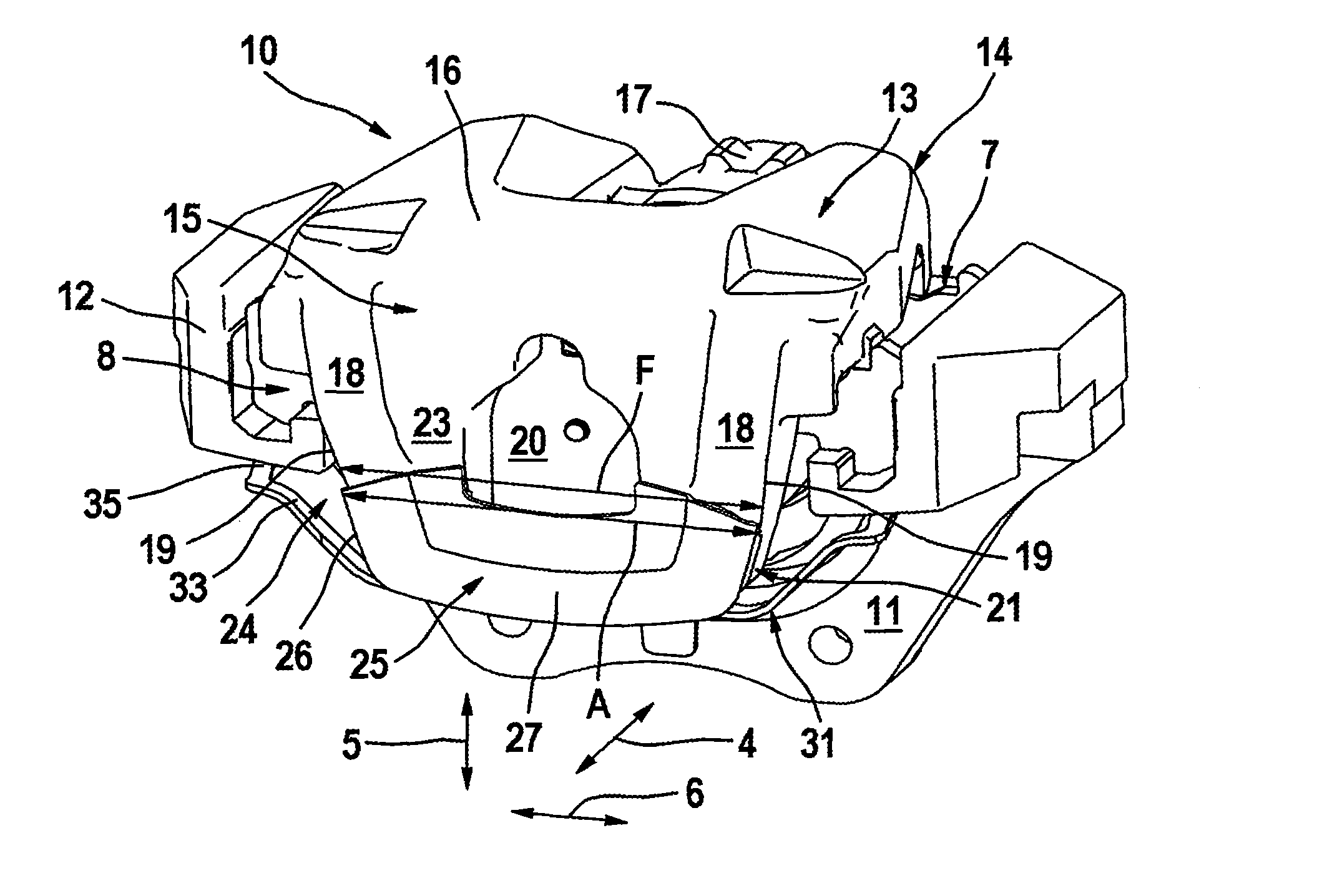
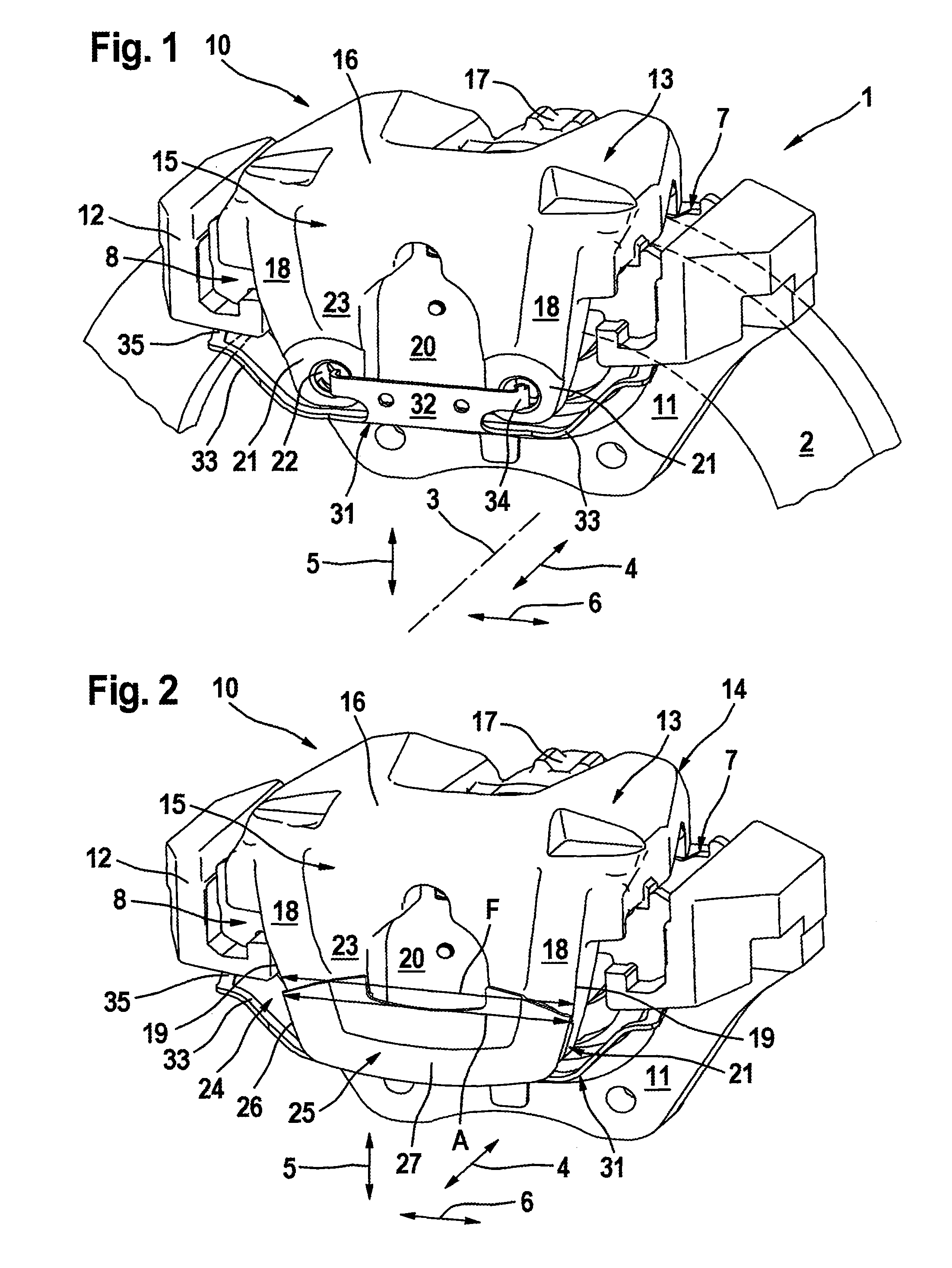
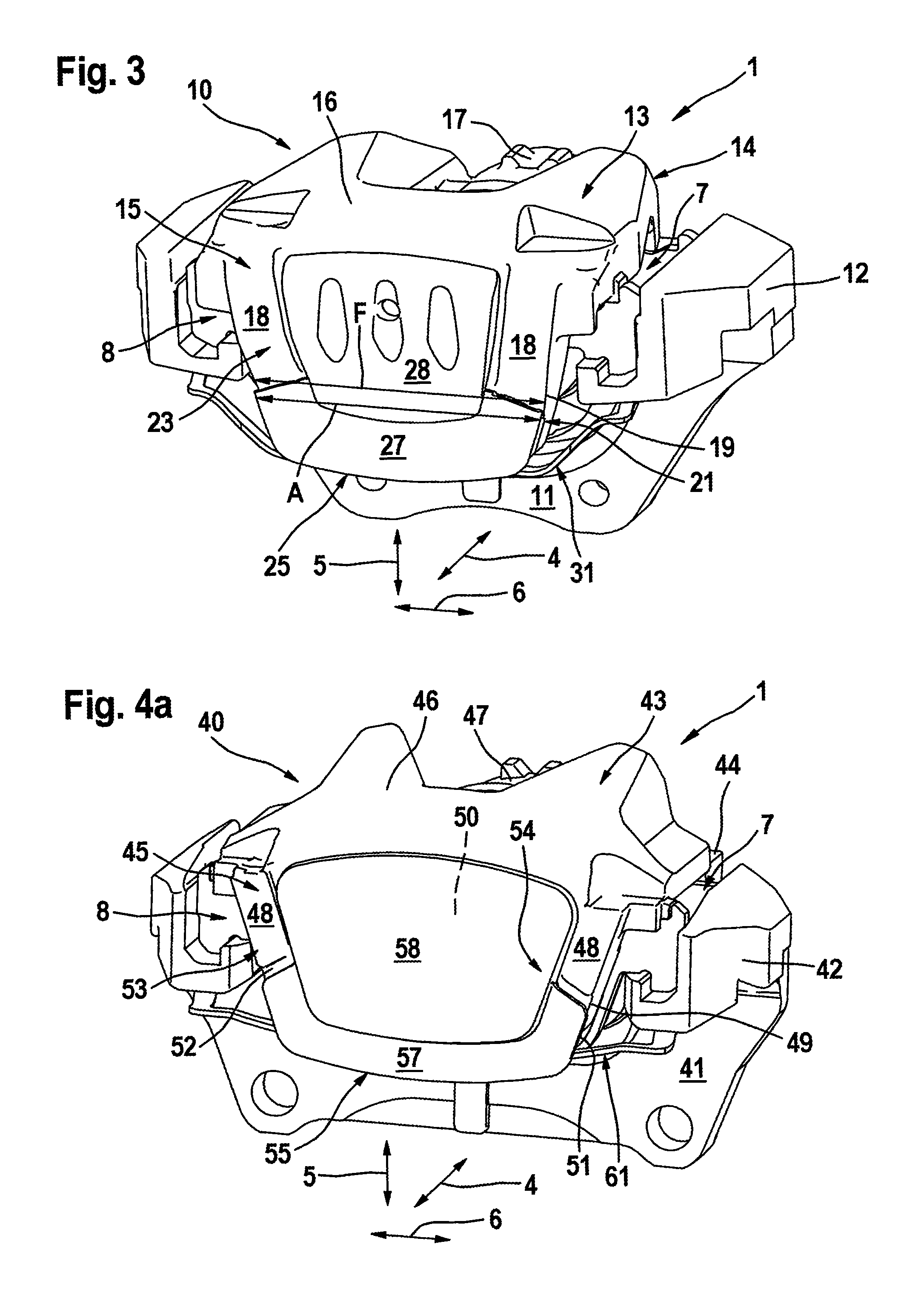
[0024]FIG. 1 to 4 show two embodiments of a brake caliper 10,40 of a disk brake 1, with FIG. 1 to 3 showing the first embodiment and FIG. 4 showing the second embodiment. In principle, both embodiments are of identical construction, wherein said embodiments differ with regard to the protective screens and geometric details. However, the following basic description applies to both embodiments. FIG. 1 shows a perspective view of a brake caliper 10 of a disk brake 1 with a caliper housing 13 and a vehicle-side bracket 11 without a protective screen. FIGS. 2 to 4 illustrate different protective screens 25, 25′, 55, 55′ mounted on the brake calipers 10,40.

[0025]The brake caliper 10,40 engages around a brake disk 2 which is mounted so as to be rotatable about the rotational axis 3. The axial direction 4, radial direction 5 and circumferential direction 6 are aligned in relation to the rotational axis 3. The caliper housing 13,43 comprises an axially inner housing limb 14,44 which comprise...


PUM


Abstract

A disk brake having a brake disk, a brake caliper including a bracket, a caliper housing and a brake lining. The bracket and the caliper housing engage axially around the brake disk, with the caliper housing and the brake lining movable in an axial direction. The caliper housing has outer housing limb comprising two housing fingers which run substantially in a radial direction and which span a limb window situated between them and which is open in the direction of the rotational axis, with the housing fingers having one end section facing the rotational axis. A protective screen covers end sections of the housing fingers and conceals a section of the limb window that faces the rotational axis, with an outer dimension of the protective screen in a circumferential direction such that a transition between the protective screen and the housing fingers is substantially stepless in an axial projection.

Description

CROSS REFERENCE TO RELATED APPLICATIONS[0001]This application is the U.S. national phase application of PCT International Application No. PCT / EP2007 / 060740, filed Oct. 10, 2007, which claims priority to German Patent Application No. DE102006055717.4, filed Nov. 23, 2006 and German Patent Application No. DE102007033165.9, filed Jul. 17, 2007, the contents of such applications being incorporated by reference herein.BACKGROUND OF THE INVENTION[0002]1. Field of the Invention[0003]The invention relates to a disk brake.[0004]2. Description of the Related Art[0005]The invention relates to a disk brake having at least one brake disk, which is mounted so as to be rotatable about a rotational axis, and having a brake caliper, which brake caliper has a bracket which is fixed with respect to the vehicle, a caliper housing and at least one brake lining. Here, the bracket and the caliper housing engage axially around the brake disk, with the caliper housing and the brake lining being mounted on t...

Claims


Application Information

Patent Timeline
Patent Type & Authority Patents(United States)
IPC IPC(8): F16D65/02
CPCF16D55/226F16D2055/0012F16D2055/0037F16D2055/0041F16D65/095
Inventor BACH, UWEHEINZ, STEFANBOGENSCHUTZ, PETERSEFO, AHMED
Owner CONTINENTAL TEVES AG & CO OHG
Why Eureka
Try Eureka