
Portable electronic apparatus

a portable electronic and electronic equipment technology, applied in the direction of electrical apparatus construction details, substation equipment, transportation and packaging, etc., can solve the problems of difficult to ensure the conventional heat dissipation route in the portable electronic apparatus described, and the user of the apparatus an unpleasant feeling, so as to ensure the heat dissipation of the heating component

Active Publication Date: 2012-10-02
KYOCERA CORP
View PDF13 Cites 12 Cited by
  • Summary
  • Abstract
  • Description
  • Claims
  • Application Information

AI Technical Summary

Benefits of technology

The present invention is about a structure for dissipating heat from an internal heating component in a portable electronic apparatus. The invention includes a housing, a circuit board, a thermally conductive member, and a battery. The thermally conductive member is formed by a covering member for covering the electronic component and is in contact with the electronic component or the battery. The battery is preferably arranged opposite to the thermally conductive member on a side where the circuit board is arranged opposed to the thermally conductive member. The invention also includes a charge control unit for controlling the charge of the battery and a temperature detection unit for detecting temperature of the battery or temperature near the battery. The portable electronic apparatus further includes an operational member with a key operational part, which is exposed outside of the housing through an opening formed in the housing. The technical effects of the invention include improved heat dissipation, reduced battery overheating, and improved operational performance of the portable electronic apparatus.

Problems solved by technology

Thus, if the housing is locally heated, the heat from the heating component is transferred to user's hand or face during use, which gives the user of the apparatus an unpleasant feeling.
However, it is difficult to ensure a conventional heat dissipation route in the portable electronic apparatus described above.

Method used


Image

  • Portable electronic apparatus
  • Portable electronic apparatus
  • Portable electronic apparatus

Examples


Embodiment Construction

[0020]Preferred embodiments of the present invention will now be described with reference to the accompanying drawings.

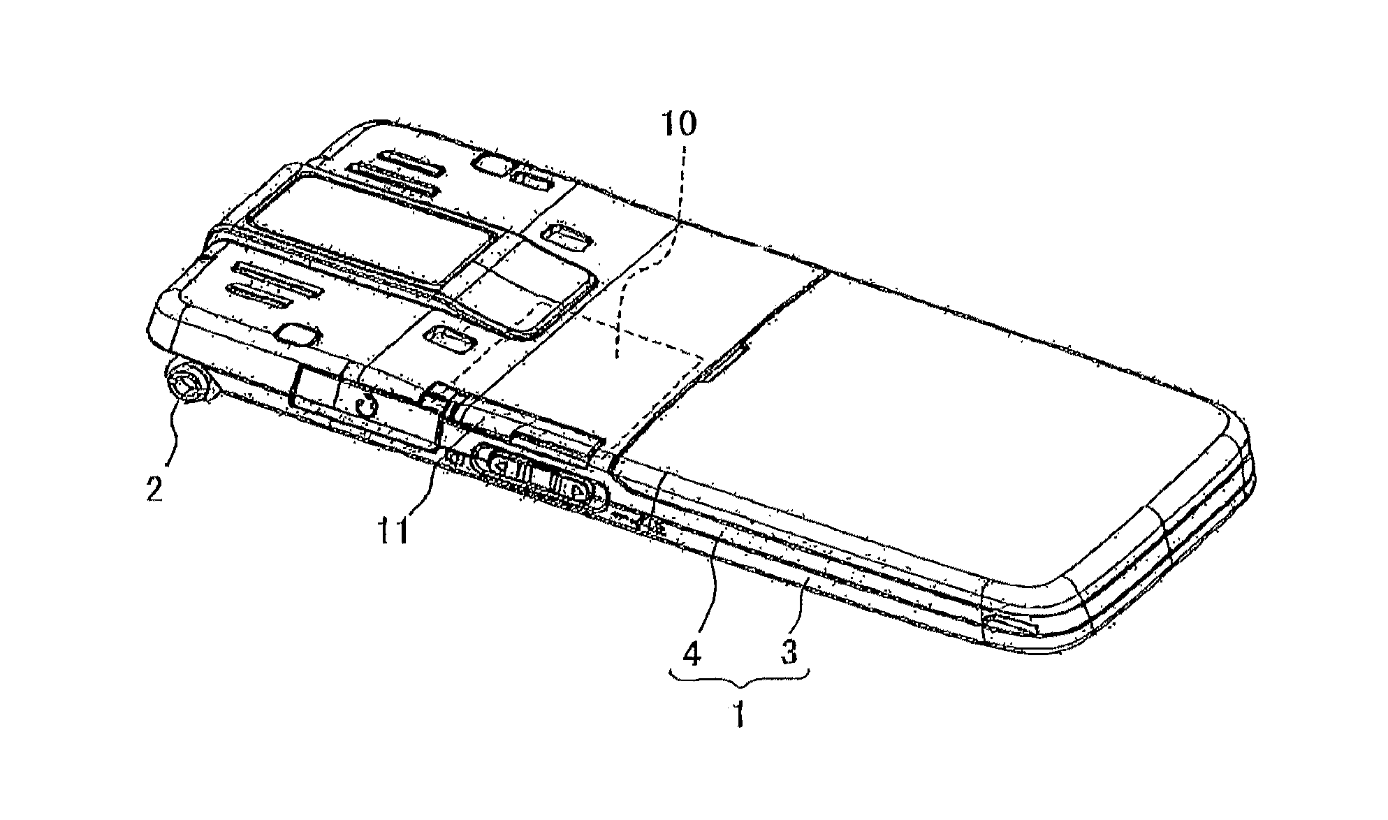
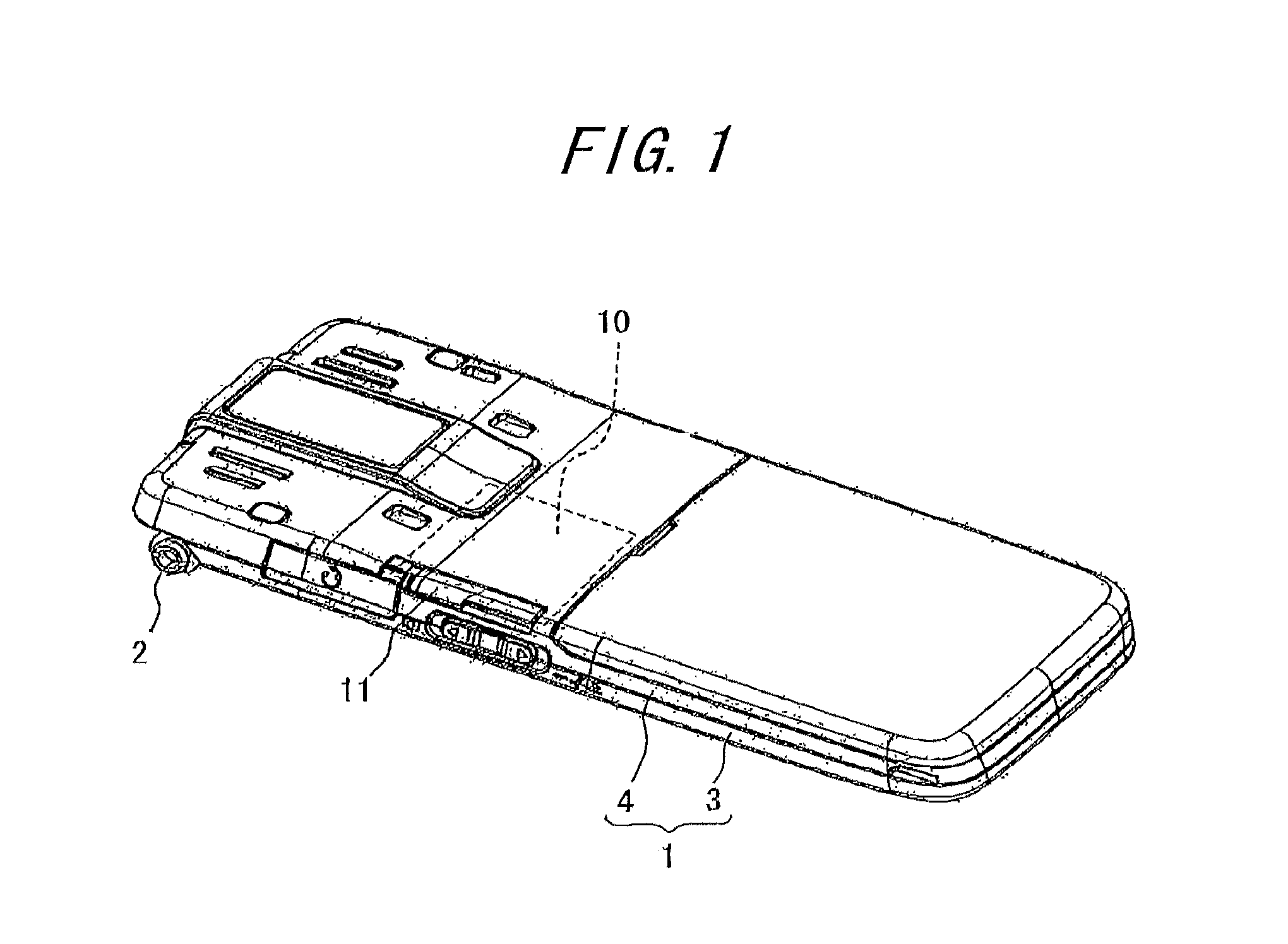
[0021]FIG. 1 shows a perspective view of a key side housing of a cellular phone as an example of a portable electronic apparatus according to an embodiment of the present invention.

[0022]As shown in FIG. 1, the key side housing 1 of the cellular phone forms a fold type cellular phone, cooperating with an indicator side housing (not shown) which is attached by a hinge 2 on one end of the key side housing 1. The key side housing 1 is formed by putting a key front case 3 and key rear case 4 on top of one another, and the key front case 3 has a key operational part (not shown) exposed to the outside of the housing 1 through an opening which is formed in the key front case 3. On the key front case 3, a key detection unit (not shown) comprising, for example, a metal dome seat and a button key to press the metal dome is mounted to detect an operational state of various ope...


PUM


Abstract

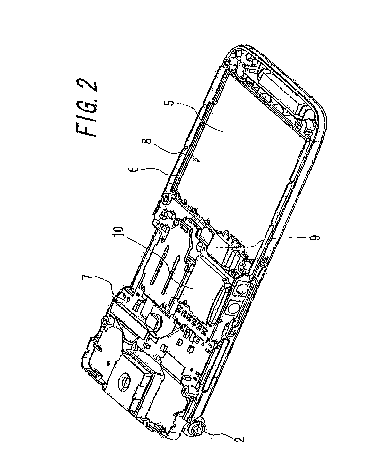
To provide a structure to dissipate heat from an internal heating component efficiently for a miniaturized, thin portable electronic apparatus. The portable electronic apparatus comprises a housing 1, a circuit board 7 accommodated in the housing and mounted with an electronic component on a surface on one side of the circuit board, a thermally conductive member 6 arranged opposite to the surface on one side of the circuit board and having thermal conductive property, and a battery accommodated in a battery chamber 8 formed in the housing. The thermally conductive member 6 forms at least a part of the battery chamber 8.

Description

CROSS-REFERENCE TO RELATED APPLICATIONS[0001]This application is a U.S. National Phase of International Patent Application No. PCT / JP2007 / 072687 filed Nov. 22, 2007, which claims priority to Japanese Patent Application No. 2006-316251 filed Nov. 22, 2006, the disclosures of which are herein incorporated by reference in their entirety.TECHNICAL FIELD[0002]The present invention is related to a portable electronic apparatus.BACKGROUND ART[0003]A portable electronic apparatus such as a cellular phone or a PDA (Personal Digital Assistant) as a typical example tends to have the increased number of components, among others, heating components, as the functionality is increasingly enhanced, and a housing of the portable electronic apparatus can be locally heated by the heating components. Particularly, in a portable electronic apparatus, heat from a heating component tends to stay inside. Thus, if the housing is locally heated, the heat from the heating component is transferred to user's ha...

Claims


Application Information

Patent Timeline
Patent Type & Authority Patents(United States)
IPC IPC(8): H02J7/04H05K7/20
CPCH04B1/036H04B1/3883H04M1/026H05K7/20445H04M1/0262
Inventor NAKAJIMA, MASAYOSHIITO, TAKASHI
Owner KYOCERA CORP
Learn More