Signal processing device for biological observation apparatus

a biological observation and processing device technology, applied in the direction of instruments, optical radiation measurement, diagnostics using spectroscopy, etc., can solve the problems of not being able to achieve the precision or reliability of a spectral signal electrically generated, image displayed on the monitor not becoming an image of a color tone suitable for observation of tissue information of a desired deep portion of a biological tissue,

Active Publication Date: 2012-10-02
OLYMPUS CORP
View PDF24 Cites 72 Cited by
  • Summary
  • Abstract
  • Description
  • Claims
  • Application Information

AI Technical Summary

Benefits of technology

[0010]The present invention is made in view of the above described circumstances, and has an object to provide a signal processing device for a biological observation apparatus which can adjust tissue information of a desired deep portion of a biological tissue based on a spectral image obtained by signal processing to image information in a color tone suitable for observation.
[0011]Further, the present invention has an object to provide a biological observation apparatus including a function of electrically creating a spectral signal from a biological signal, and suitable for obtaining a spectral signal with higher precision or reliability.

Problems solved by technology

However, for example, in the apparatus disclosed in the above described Japanese Patent Laid-Open No. 2003-93336, an spectral image is obtained by signal processing, and a filter for generating narrow band RGB light is not required, but since the obtained spectral image is simply outputted to a monitor, there arises a fear that the image displayed on the monitor does not become an image of a color tone suitable for observation of tissue information of a desired deep portion of a biological tissue.
Therefore, there is a disadvantage of securing precision or reliability of a spectral signal electrically generated.

Method used


Image

  • Signal processing device for biological observation apparatus
  • Signal processing device for biological observation apparatus
  • Signal processing device for biological observation apparatus

Examples


embodiment 2

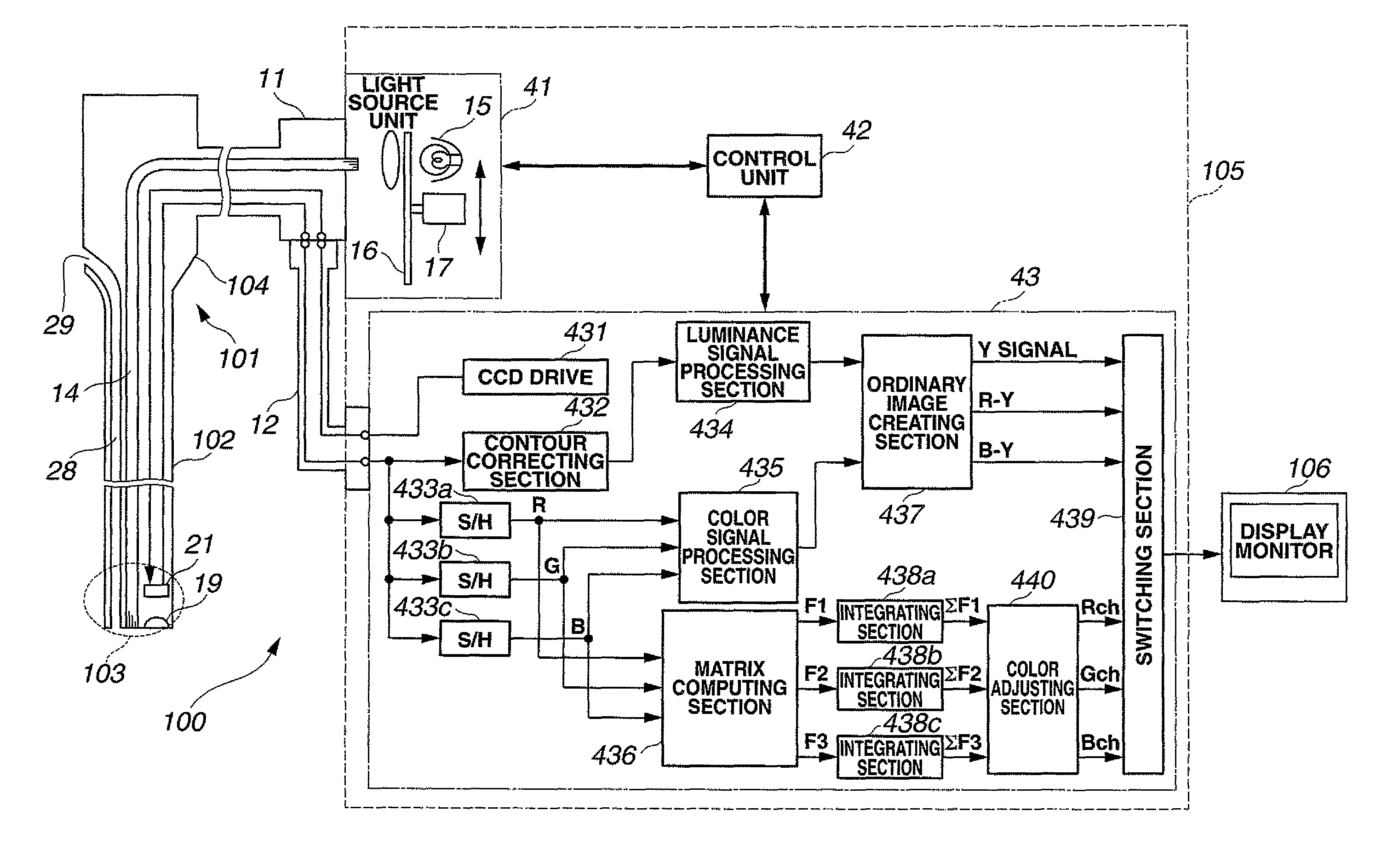
[0224]FIG. 27 is a block diagram showing a configuration of an electronic endoscope apparatus according to an embodiment 2 of the present invention.

[0225]Since the embodiment 2 is substantially the same as the embodiment 1, only the different point will be described, and the explanation of the same components will be omitted by being assigned with the same reference numerals and characters as in the first embodiment.

[0226]The present embodiment mainly differs from the embodiment 1 in the light source unit 41 which performs control of the illumination light quantity. In the present embodiment, control of the light quantity irradiated from the light source unit 41 is performed by current control of the lamp 15 instead of the chopper. More specifically, a current control section 18 is provided at the lamp 15 shown in FIG. 27.

[0227]As an operation of the present embodiment, the control unit 42 controls the current control section 18 and performs control of a current flowing into the lam...

embodiment 3

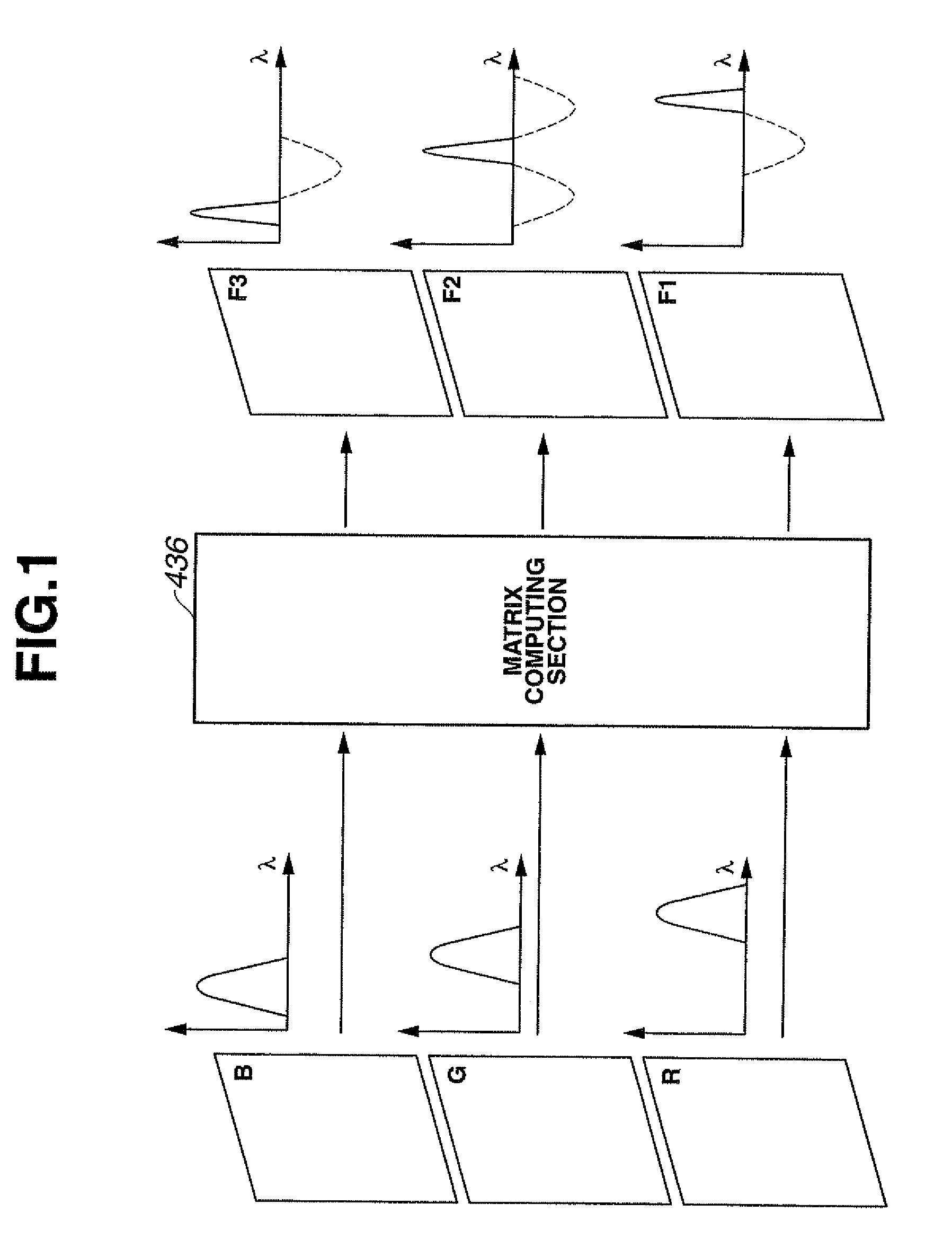
[0230]FIG. 28 is a block diagram showing a configuration of a matrix computing section according to an embodiment 3.

[0231]Since the embodiment 3 is substantially the same as the embodiment 1, only the different point will be described, and the explanation of the same components will be omitted by assigning them with the same reference numerals and characters as the embodiment 1.

[0232]The present embodiment differs from the embodiment 1 mainly in the configuration of the matrix computing section 436. In the embodiment 1, the matrix computation is performed by so-called hardware processing by the electronic circuit, but in the present embodiment of FIG. 28, the matrix computation is performed by numeric data processing (processing by software using a program).

[0233]A concrete configuration of the matrix computing section 436 in the present embodiment is shown in FIG. 28. The matrix computing section 436 has an image memory 50 which stores respective color image signals of R, G and B. ...

embodiment 4

[0240]FIG. 29 and FIG. 30 relate to an embodiment 4 of the present invention, and FIG. 29 is a block diagram showing a configuration of an electronic endoscope apparatus, whereas FIG. 30 is a diagram showing charge storage time of a CCD of FIG. 29.

[0241]Since the embodiment 4 is substantially the same as the embodiment 1, only the point differing from the embodiment 1 will be described, and the explanation of the same components will be omitted by assigning them with the same reference numerals and characters as in the embodiment 1.

[0242]The present embodiment mainly differs from the embodiment 1 in the light source unit 41 and the CCD 21. In the embodiment 1, a so-called simultaneous method in which color filters shown in FIG. 6 is provided at the CCD 21, and the color signals are created by the color filters is adopted, but in the present embodiment, a so-called frame sequential method in which illumination light is illuminated in the sequence of R, G and G in one frame term to cr...


PUM


Abstract

Tissue information of a desired deep portion of a biological tissue based on a spectral image obtained from signal processing is adjusted to image information in a color tone suitable for observation. Outputs of a matrix computing section 436 are respectively connected to integrating sections 438a to 438c, and after integrating computation is performed for them, color conversion computation is performed for respective spectral image signals ΣF1 to ΣF3 in a color adjusting section 440, spectral color channel image signals Rch, Gch and Bch are created from the spectral image signals ΣF1 to ΣF3, and images of the spectral color channel images Rch, Gch and Bch are sent to a display monitor 106 via a switching section 439.

Description

TECHNICAL FIELD[0001]The present invention relates to a signal processing device for a biological observation apparatus which uses a color image signal obtained by picking up an image of a living body and displays the image on a monitor as a spectral image by signal processing.BACKGROUND ART[0002]Conventionally, as a biological observation apparatus, an endoscope apparatus which irradiates illumination light and obtains an endoscope image in a body cavity has been widely used. In an endoscope apparatus of this kind, an electronic endoscope having image pick up means which guides illumination light from a light source into a body cavity by using a light guide or the like and picks up an image of a subject by its feedback light, and by performing signal processing of an image pickup signal from the image pickup means by a video processor, the endoscope image is displayed on an observation monitor so that an observation region of a patient or the like is observed.[0003]When ordinary bi...

Claims


Application Information

Patent Timeline
Patent Type & Authority Patents(United States)
IPC IPC(8): A62B1/04A61B1/04
CPCA61B1/00009A61B1/00186A61B1/045A61B1/0638A61B1/0646A61B5/0075A61B5/0084G01J3/32G01J3/50G01N21/255G02B23/24G01J3/501G01J3/513G01J2003/1213G01J2003/1221H04N2005/2255A61B5/7242A61B1/000094A61B1/0655H04N23/555H04N7/18
Inventor GONO, KAZUHIROAMANO, SHOICHITAKAHASHI, TOMOYAOHSHIMA, MUTSUMI
Owner OLYMPUS CORP
Why Eureka
Try Eureka