Optical unit with shake correcting function

a technology of optical units and functions, applied in the field of optical units with shake correcting functions, can solve the problems of high labor requirements for assembling, low vibration resistance, insufficient shake correcting torque and quick response, etc., and achieve the effect of small torqu

Active Publication Date: 2012-10-02
SANKYO SEIKI MFG CO LTD
View PDF5 Cites 29 Cited by
  • Summary
  • Abstract
  • Description
  • Claims
  • Application Information

AI Technical Summary

Benefits of technology

[0009]In view of the problems described above, at least an embodiment of the first present invention may advantageously provide an optical unit with shake correcting function in which shake of a movable module is corrected with a small torque and a quick response without mechanically connecting the fixed body and the movable module through a drive mechanism.
[0010]Further, in view of the problems described above, at least an embodiment of the second present invention may advantageously provide an optical unit with shake correcting function in which a sufficient drive force for swinging a lens drive module on which a lens and an imaging element are mounted is capable of obtaining even when the optical unit is made smaller and thinner.

Problems solved by technology

However, in the case that the actuator utilizing a piezo-electric element is used like the structure disclosed in the above-mentioned former Patent Reference, the fixed body and the movable module are mechanically connected with each other through the actuator and thus much labor is required for assembling and vibration resistance may be low.
Further, even in a case that the swing mechanism is structured of a drive coil and a drive magnet, it is insufficient to correct shake with a small torque and a quick response.

Method used


Image

  • Optical unit with shake correcting function
  • Optical unit with shake correcting function
  • Optical unit with shake correcting function

Examples


Embodiment Construction

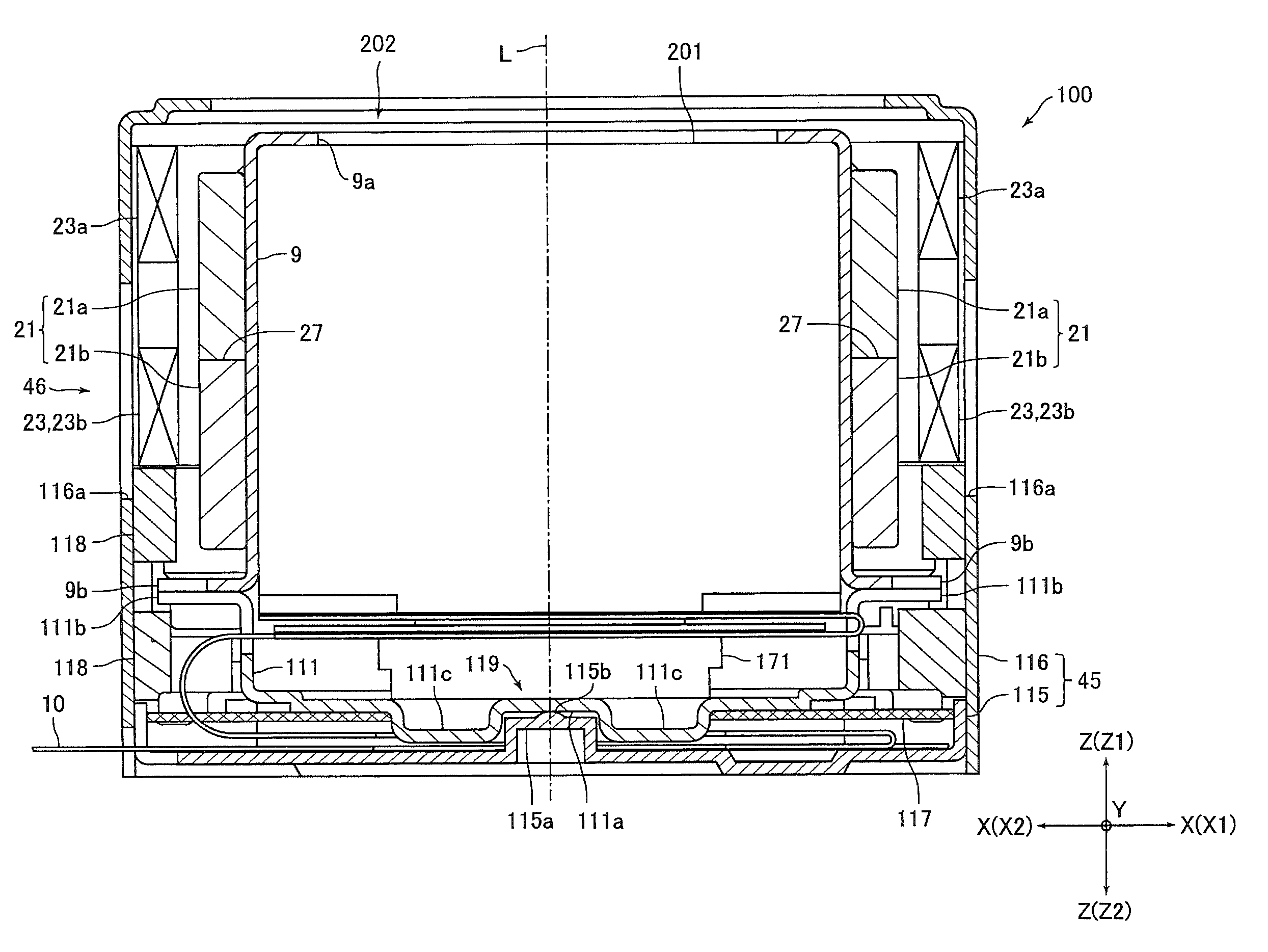
[0073]An embodiment of the present invention in which a magnetic drive mechanism for shake correction is structured on both sides of a movable module will be described below with reference to the accompanying drawings. In the following description, three directions perpendicular to each other, i.e., an X-axis, a Y-axis and a Z-axis are set in a fixed body, and the direction along an optical axis “L” (lens optical axis) is set to be the Z-axis. Therefore, in the following description, swing around the X-axis corresponds to so-called pitching (vertical swing), swing around the Y-axis corresponds to so-called yawing (lateral swing) and swing around the Z-axis corresponds to so-called rolling. Further, in the following description, “object to be photographed side” is described as “front side” or “upper side”, and “opposite side to the object to be photographed side” is described as “rear side” or “lower side”.

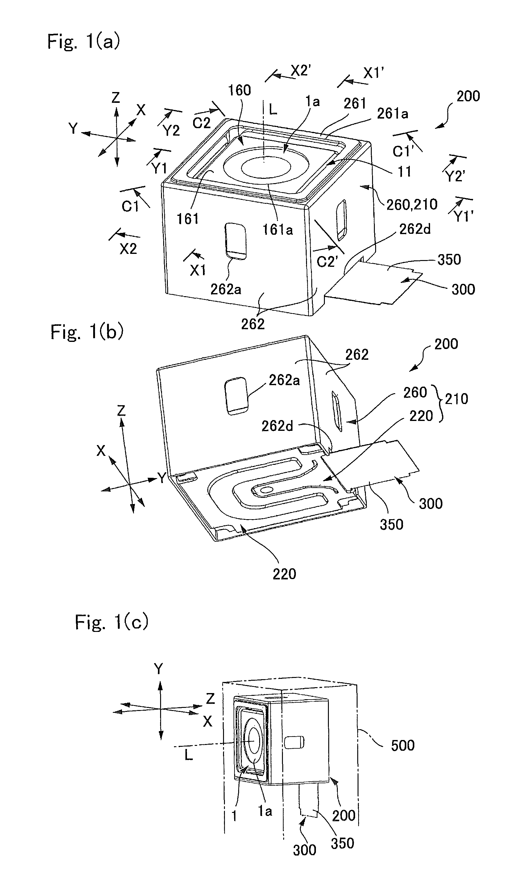
[0074]FIGS. 1(a), 1(b) and 1(c) are explanatory views showing an entire optica...


PUM


Abstract

An optical unit with shake correcting function may include a movable module having a lens, a fixed body supporting the movable module, a shake detection sensor for detecting shake of the movable module, and at least one pair of magnetic drive mechanism for shake correction which is structured on both sides of the movable module so that the movable module is swung with respect to the fixed body on the basis of detection result of the shake detection sensor to correct the shake of the movable module. The magnetic drive mechanism for shake correction is disposed so that a shake correction magnet is held by the fixed body and a shake correction coil is held by the movable module. Further, a shake correction coil may be disposed in a first region, where magnetic lines of force generated by a shake correction magnet are directed in directions generally going away from a supporting point part and / or a second region where magnetic lines of force generated by the shake correction magnet are directed in directions generally going toward the supporting point part.

Description

CROSS REFERENCE TO RELATED APPLICATION[0001]The present invention claims priority under 35 U.S.C. §119 to Japanese Application No. 2008-264891 filed Oct. 14, 2008, Japanese Application No. 2008-264894 filed Oct. 14, 2008, Japanese Application No. 2008-265681 filed Oct. 14, 2008, and Japanese Application No. 2009-209994 filed Sep. 11, 2009, the entire contents of which are incorporated herein by reference.FIELD OF THE INVENTION[0002]An embodiment of the present invention may relate to an optical unit with shake correcting function in which a module provided with a lens is swung to correct shake such as a shake of hand.BACKGROUND OF THE INVENTION[0003]In a photographic optical device which is mounted on a cell phone or a digital camera, a laser beam pointer, or an optical instrument such as a portable projection display device or a projection display device for car, shake is easily occurred in its optical axis when shake or external vibration is transmitted.[0004]In order to prevent t...

Claims


Application Information

Patent Timeline
Patent Type & Authority Patents(United States)
IPC IPC(8): H04N5/228G02B27/64
CPCG02B27/646H04N5/2254H04N5/2257H04N5/23248H04N5/23287H04N23/57H04N23/68H04N23/687
Inventor NAGATA, AKIHIROKARASAWA, TOSHIYUKITAKEI, YUICHITAKEDA, TADASHIISHIHARA, HISAHIROMINAMISAWA, SHINJIYANAGISAWA, KATSUSHIGEMIYAZAKI, KIYOSHI
Owner SANKYO SEIKI MFG CO LTD
Why Eureka
Try Eureka