Electric and hybrid electric powertrain for motor vehicles

a hybrid electric and motor vehicle technology, applied in the direction of belts/chains/gearings, vehicle components, vehicle components, etc., can solve the problems of battery damage, achieve the effect of accelerating to the maximum efficiency point very quickly, reducing efficiency, and high efficiency operating poin

Active Publication Date: 2006-07-06
FORD GLOBAL TECH LLC
View PDF5 Cites 22 Cited by
  • Summary
  • Abstract
  • Description
  • Claims
  • Application Information

AI Technical Summary

Benefits of technology

[0021] Due to the geared-neutral state, the electric machine can be directly coupled to the IVT input, yet be isolated from the IVT output and the drive wheels of the vehicle. This allows an electric machine alone to launch the vehicle at a higher efficiency operating point of the electric machine, rather than from a zero-speed, lower efficiency electric machine point: An electric machine, when decoupled from the vehicle or both the vehicle and the engine, can accelerate to its maximum efficiency point very quickly. After that speed is attained, the IVT can rapidly change to its desired output ratio, i.e., the driver demanded wheel power. Power saved by this efficient use of the motor is available to launch more efficiently the vehicle rapidly and smoothly. The large torque multiplication possible with an IVT also allows use of an electric machine having smaller torque and electric current capacity for the same power delivered to the drive wheels. A smaller electric machine can reduce cost of the system.
[0022] Additionally, a torque controlled IVT that isolates the electric machine and engine from the vehicle, more easily facilitates smooth engine restart after vehicle launch using the electric motor only. The higher efficiency and better operating point control of such a system also facilitates higher efficiency in recovering kinetic energy during regenerative braking down to zero vehicle speed. This reduces the need to dissipate kinetic energy in the vehicle's wheel brakes.

Problems solved by technology

The battery is compromised in this way because the cost and mass of a battery that would achieve both high power and a small state of charge excursion, a requirement for satisfactory service life, is too great.

Method used


Image

  • Electric and hybrid electric powertrain for motor vehicles
  • Electric and hybrid electric powertrain for motor vehicles
  • Electric and hybrid electric powertrain for motor vehicles

Examples


Embodiment Construction

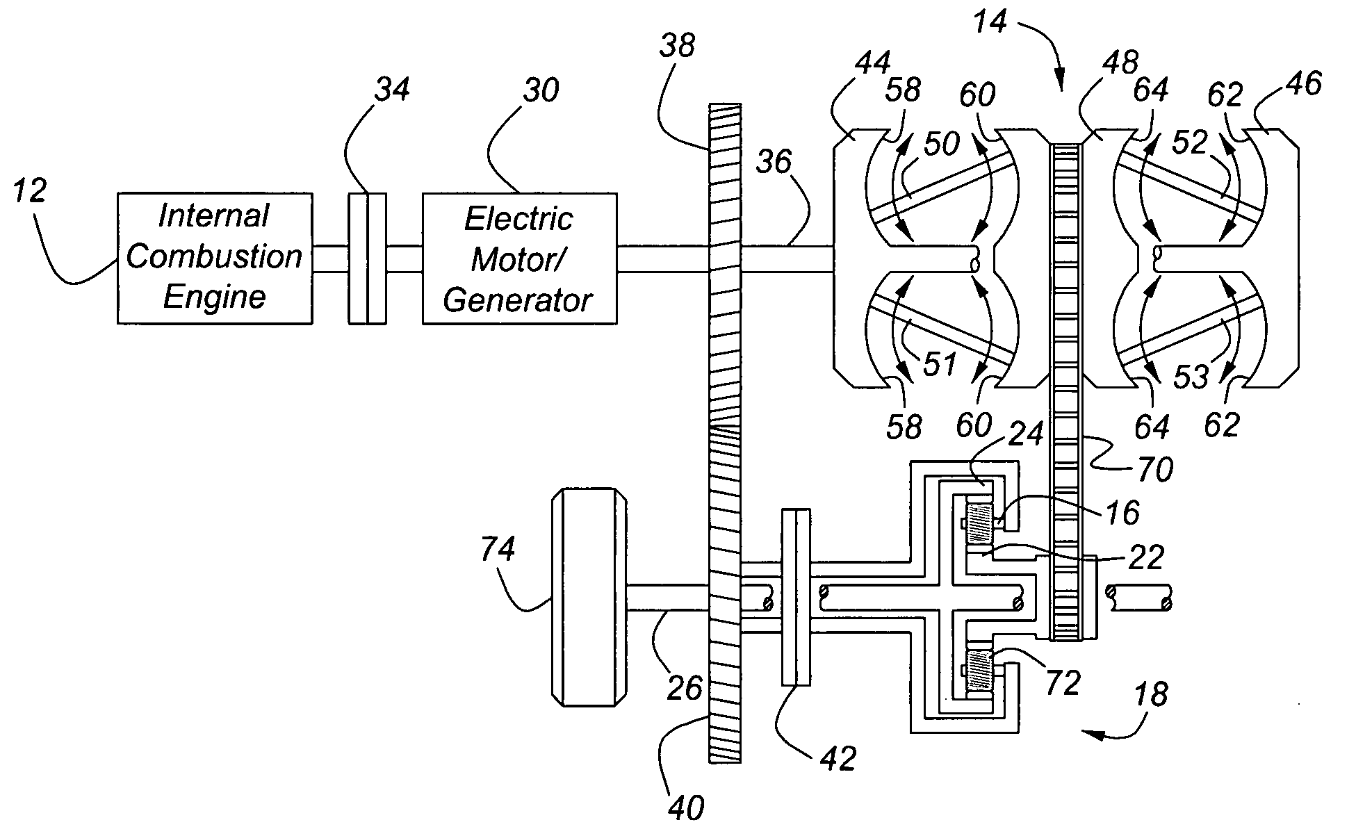
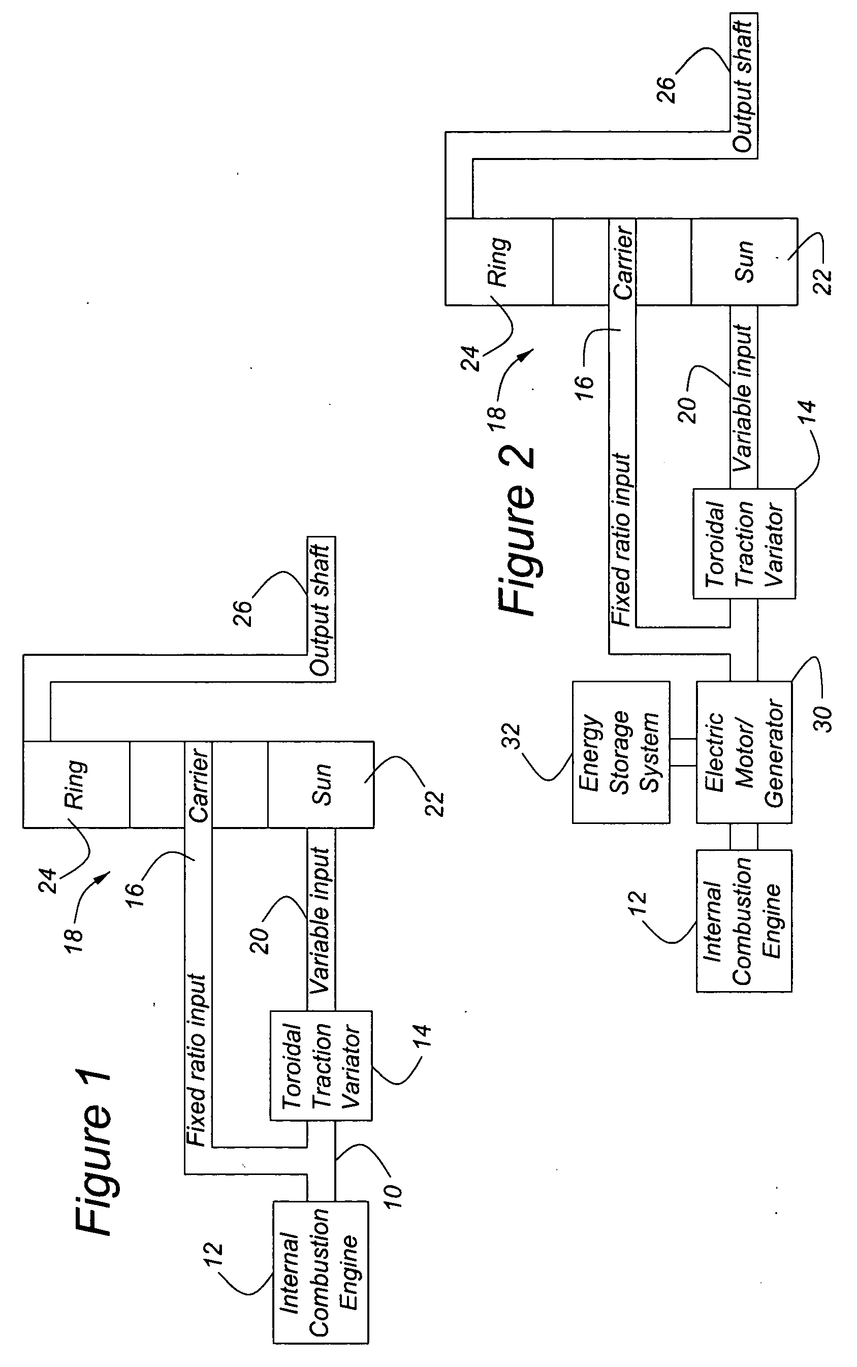
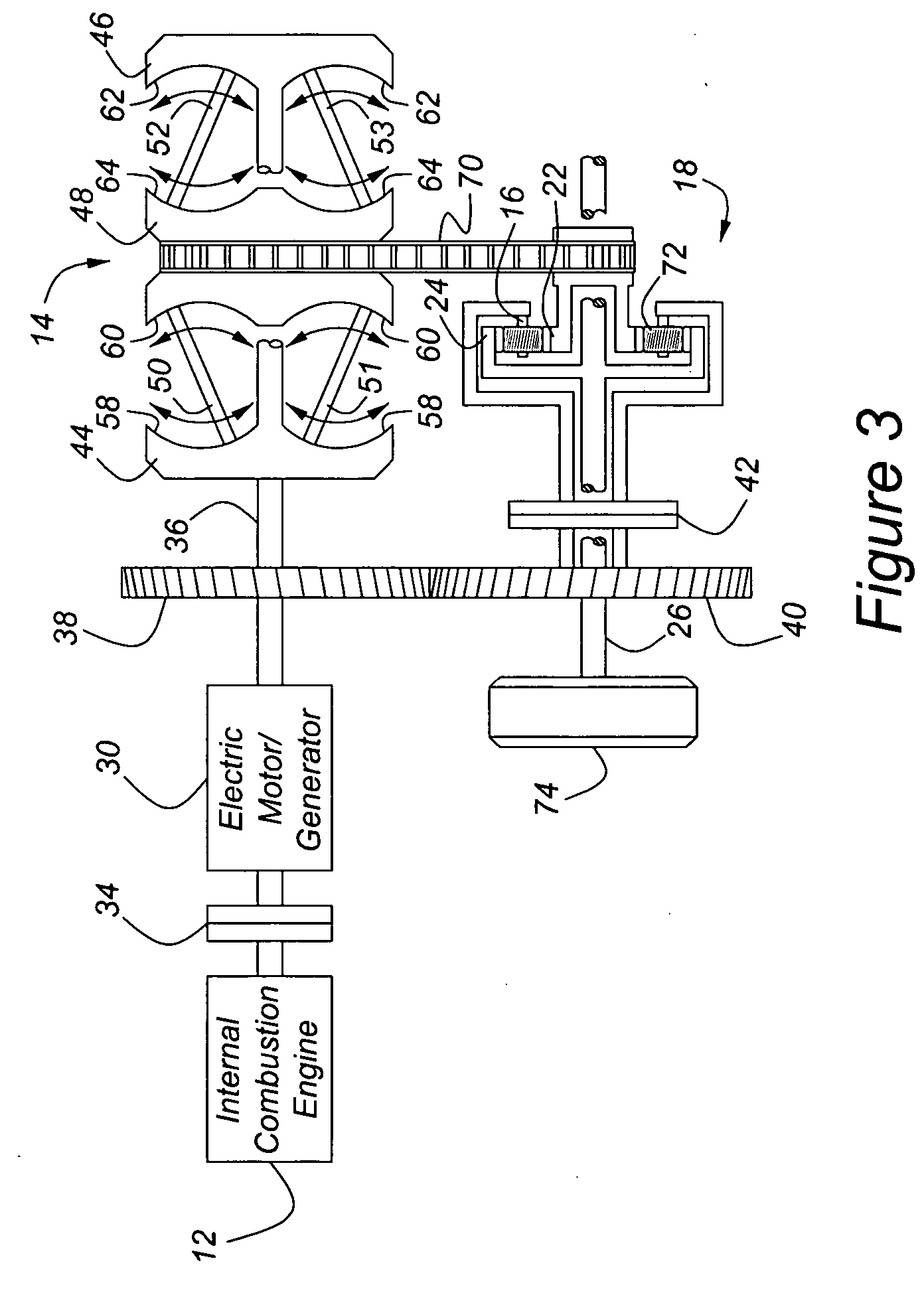
[0030] Referring first to FIG. 1, the output 10 of a prime mover 12, such as an internal combustion (IC) engine, is drivably connected to the input of a toroidal traction drive transmission 14 and to the planet pinion carrier 16 of an epicyclic transmission 18. The planet pinions supported on carrier 16 are in continuous meshing engagement with a sun gear 22 and ring gear 24 of the epicyclic transmission 18. The output 20 of the traction drive transmission 14 is driveably connected to the sun gear 22. The ring gear 24 of transmission 18 is driveably connected to an output shaft 26, to which a drive wheel of a motor vehicle is driveably connected.

[0031] To best apply the advantages of this invention, the prime mover 12 would be characterized by slow load and speed response and preferably would include any of the following group: a homogeneous charge compression ignition (HCCI) gasoline ICE, HCCI diesel ICE, and turbocharged diesel ICE. Less preferred alternatives include a Stirling ...


PUM


Abstract

A powertrain for transmitting power to a driven wheel of a motor vehicle includes a power source that includes a reversible electric machine. A first transmission includes an input driveably connected to the power source, a first output, and a mechanism for producing a stepless variable range of ratios of a speed of the output to a speed of the input. An epicyclic transmission includes a second input driveably connected to the power source, a third input driveably connected to the first output, and a second output driveably connected to a drive wheel. The transmissions produce a range of speed of the drive wheel that varies from negative to positive and includes zero.

Description

CROSS-REFERENCE TO RELATED APPLICATIONS [0001] This application is a continuation-in-part of pending U.S. application Ser. No. 11 / 030,237, filed Jan. 6, 2005. This application claims the benefit of U.S. Provisional Application No. 60 / 655,114, filed Feb. 22, 2005.BACKGROUND OF THE INVENTION [0002] This invention relates generally to hybrid powertrains for motor vehicles having two power sources or prime movers, such as an electric motor and internal combustion engine. In particular, the invention pertains to a powertrain that provides the driver with an acceptable response to a command for a change in wheel torque even though the prime mover is slow to respond to the command. [0003] Hybrid electric powertrains for motor vehicles include at least two power sources or prime movers, an electric motor or motor / generator, accessible to an electric storage unit such as a battery, and an engine, such as an internal combustion engine supplied from a fuel source. Powertrains for another type ...

Claims


Application Information

Patent Timeline
Patent Type & Authority Applications(United States)
IPC IPC(8): F16H37/02
CPCB60Y2300/785F16H37/086F16H2037/088
Inventor ROETHLER, BOBBERHAN, MICHAEL
Owner FORD GLOBAL TECH LLC
Why Eureka
Try Eureka