Motor drive apparatus having oscillation-reducing control function for output torque

A motor-driven, vibration-reducing technology, applied in engine-driven traction, AC motor control, motors, etc., can solve problems such as vehicle vibration and driver discomfort, and achieve the effect of preventing step parts

Inactive Publication Date: 2006-05-03
TOYOTA JIDOSHA KK
View PDF4 Cites 22 Cited by
  • Summary
  • Abstract
  • Description
  • Claims
  • Application Information

AI Technical Summary

Problems solved by technology

The occurrence of this step portion causes the vehicle to vibrate, which makes the driver feel uncomfortable

Method used


Image

  • Motor drive apparatus having oscillation-reducing control function for output torque
  • Motor drive apparatus having oscillation-reducing control function for output torque
  • Motor drive apparatus having oscillation-reducing control function for output torque

Examples


no. 1 example

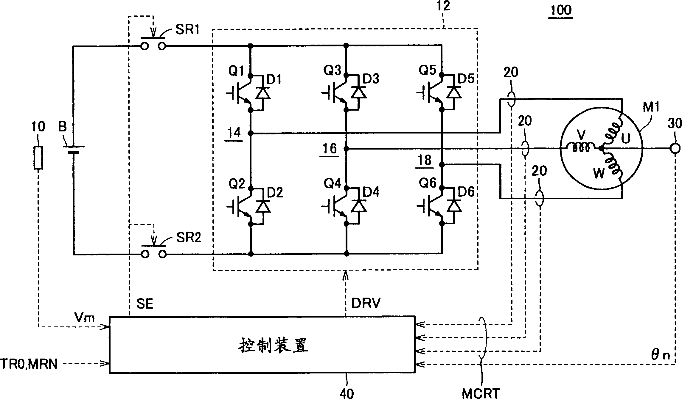
[0068] figure 1 is a schematic block diagram of the motor drive device according to the first embodiment of the present invention.

[0069] refer to figure 1 , the motor drive device 100 includes a DC power supply B, a voltage sensor 10 , an inverter 12 , a current sensor 20 , a resolver (resolver) 30 and a control device 40 .

[0070] The AC motor M1 is a drive motor for generating torque to drive drive wheels of a hybrid vehicle or an electric vehicle. The AC motor M1 also functions as a generator driven by the engine and as an electric motor for the engine, and thus has, for example, the ability to start the engine.

[0071] Inverter 12 is composed of U-phase arm 14 , V-phase arm 16 and W-phase arm 18 . U-phase arm 14 , V-phase arm 16 , and W-phase arm 18 are provided in parallel (in parallel) between the power supply line and the ground line.

[0072] U-phase arm 14 is composed of NPN transistors Q1, Q2 connected in series. V-phase arm 16 is composed of NPN transist...

no. 2 example

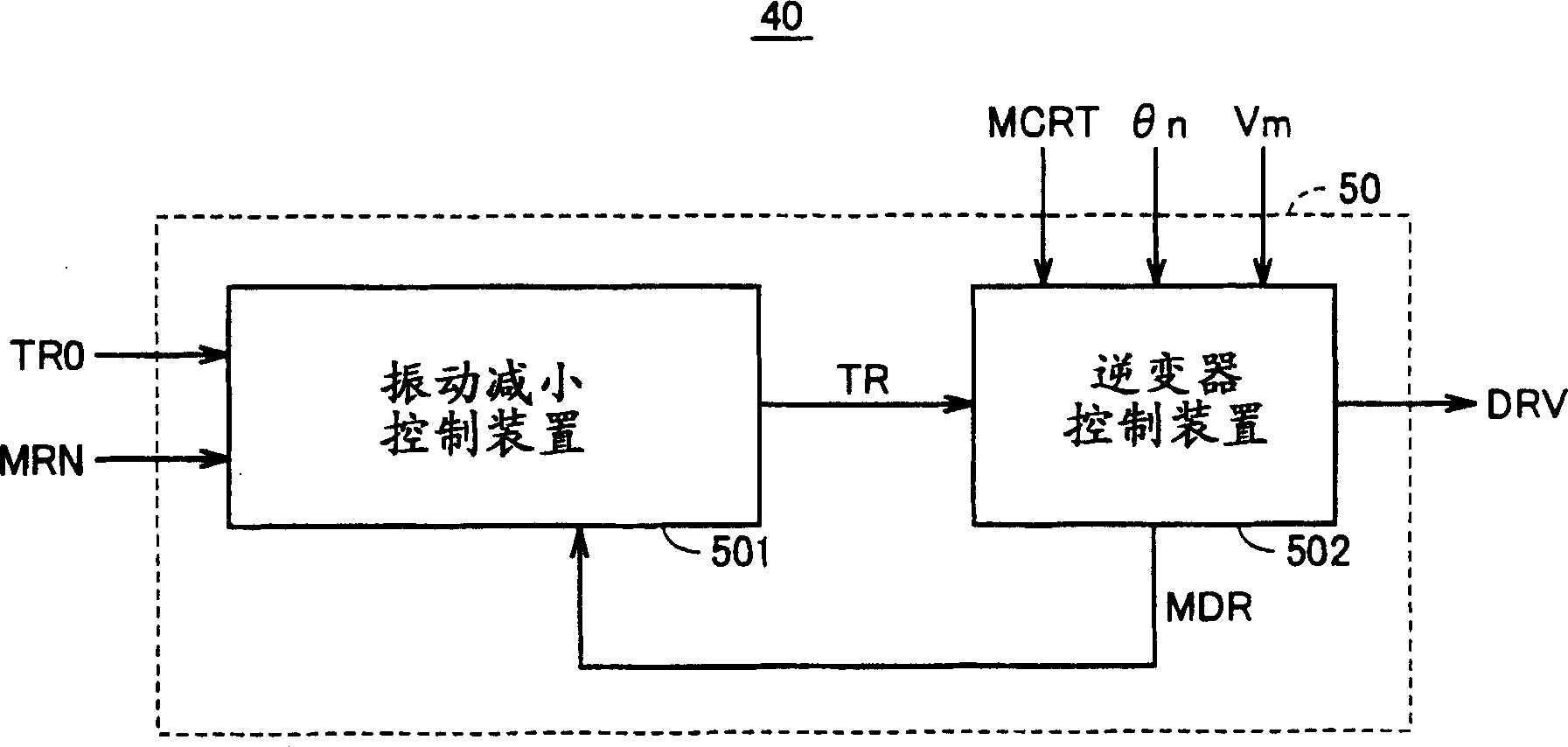
[0156] As described above in connection with the first embodiment, the vibration reduction control device 501 of the present invention generates the vibration reduction torque Δtr based on the reverse phase component of the rotation number variation component ΔMRN of the motor rotation number MRN. The inverter control device 502 adds the externally supplied torque command value TR0 to the vibration reducing torque Δtr, and the sum is used as a final torque command value TR for driving the AC motor M1. Thereby, the vibration of the output torque of AC motor M1 can be reduced, and comfortable driving can be realized. In particular, the vibration reduction control is effective in any situation that induces vibration of the vehicle such as a sudden change in the torque command value TR0 of the AC motor M1.

[0157] However, when the vehicle is in a normal running state or stopped and in a no-load state, any slight change in the output torque will cause any behavior of the vehicle,...

no. 3 example

[0184] In the second embodiment described above, the method of employing the vibration reduction control in the case where the variation amount of the drive torque applied to the drive wheels is large has been described.

[0185] as combined Figure 13A-1 As described in 3C, the amount of change in the drive torque output from motor generator MG2 varies depending on the state of the vehicle.

[0186] Therefore, when the vibration reducing control is performed, the magnitude of the vibration reducing torque can be changed according to the change amount of the driving torque to enhance the effect of the vibration reducing control.

[0187] Specifically, when the change amount of the driving torque is large, the vibration reduction torque correction unit 62 of the vibration reduction control device 501 corrects by multiplying the vibration reduction torque Δtr0 by a large correction coefficient Km. For example, when the engine is started, a large torque is applied to motor gener...


PUM


Abstract

The present invention relates to a motor drive device having a vibration reduction control function for output torque. Under the condition that vibration reduction control is performed while PWM control is performed, a vibration reduction torque (Δtr) whose phase is opposite to that of the motor revolution variation component is generated, and the vibration reduction torque (Δtr) and the torque The final torque command value (TR) of the sum of the command values ​​(TR0) is used to drive the AC motor (M1). In the transitional state where the PWM control mode is switched to the overmodulation control mode, the vibration reducing torque (Δtr) determined by multiplying the vibration reducing torque (Δtr0) by the correction coefficient (Km) according to the modulation rate changes along with The correction coefficient (Km) decreases gradually, and becomes almost zero when the control mode is switched. Thus, the vibration reducing torque (Δtr) does not have any step portion that occurs in the vibration reducing torque (Δtr0) at the time of switching the control mode. Therefore, the vibration of the output torque of the AC motor can be reduced.

Description

[0001] This non-provisional application is based on Japanese Patent Applications No. 2004-295076 and No. 2004-337804 filed with the Japan Patent Office on October 7, 2004 and November 22, 2004, respectively, the entire contents of which are hereby incorporated by reference for reference. technical field [0002] The invention relates to a motor drive device, in particular to a motor drive device with a vibration reduction control function for output torque. Background technique [0003] Hybrid vehicles and electric vehicles have recently received great attention as environmentally friendly vehicles. As its prime power source, a hybrid vehicle has a direct current (DC) power source, an inverter, and a motor driven by the inverter in addition to a conventional engine. More specifically, the engine is driven to obtain a motive power source, and a direct current voltage from a direct current power source is converted into an alternating current (AC) voltage via an inverter for ...

Claims


Application Information

Patent Timeline
Patent Type & Authority Applications(China)
IPC IPC(8): H02P27/06B60L50/16
CPCY02T10/64Y02T10/7072
Inventor 矢口英明
Owner TOYOTA JIDOSHA KK
Why Eureka
Try Eureka