
Wind power plant generation device

A technology for wind power generation devices and generators, which is applied in the direction of wind power engines, wind power motor combinations, transmission devices, etc., which can solve the problems of complex motor structure and difficult processing and manufacturing, and achieve the effects of good power quality, simplified structure, and cost saving

Inactive Publication Date: 2009-12-09
INST OF ELECTRICAL ENG CHINESE ACAD OF SCI
View PDF4 Cites 22 Cited by
  • Summary
  • Abstract
  • Description
  • Claims
  • Application Information

AI Technical Summary

Problems solved by technology

However, this kind of motor has complex structure, difficult processing and manufacturing, and there are also maintenance problems of brushes and slip rings.

Method used


Image

  • Wind power plant generation device
  • Wind power plant generation device
  • Wind power plant generation device

Examples


Embodiment Construction

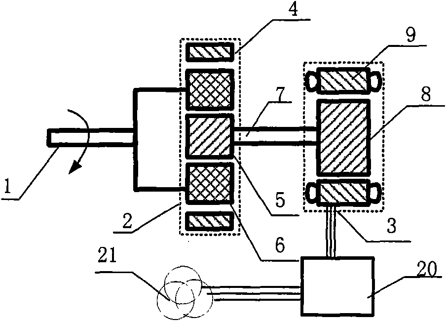
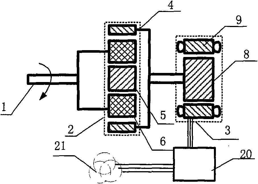
[0028] The invention includes two parts: an active stepless speed regulating device and a wind power generating device.

[0029] The speed regulating device of the present invention is as figure 1 and figure 2As shown, it includes a motor 3 , a planetary gear 2 and a power converter 20 . Planetary gear 2 is made up of outer ring gear 4 , planet carrier 6 and sun gear 5 . The power converter 20 supplies power to the speed-regulating motor 3 , the mechanical output shaft 1 is connected to the planet carrier 6 of the planetary gear 2 , and the rotor 8 of the speed-regulating motor 3 is connected to the sun gear 5 of the planetary gear 2 through the mechanical output shaft 7 . Planetary gear 2 has the following relationship:

[0030] ω s =(1+ρ)×ω c -ω r / ρ

[0031] ω c =ρ×ω s / (1+ρ)+ω r / (1+ρ)

[0032] ω r =(1+ρ)×ω c -ρ×ω s

[0033] T s =ρ×T c / (1+ρ)=ρ×T r (1)

[0034] T r =T c / (1+ρ)

[0035] ρ = number of teeth of sun gear / number of teet...


PUM


Abstract

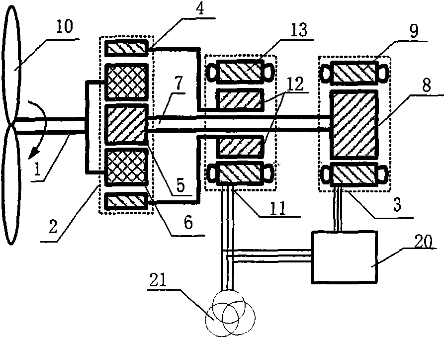
A wind power plant generation device is characterized in that a wind machine (10) is connected with a planet carrier (6) of a planetary gear (2), and an outer gear ring (4) of the planetary gear (2) is connected with a rotor of a generator (11) or with a rotor of a speed regulating motor (3). The stator-winding of the generator (11) is directly connected with the electric network. A sun gear (5) of the planetary gear (2) is connected with the rotor of the speed regulating motor (3) or with the rotor of the generator (11). A power inverter (20) is used for providing power for the stator-winding of the speed regulating motor (3).

Description

technical field [0001] The invention relates to wind power generating equipment, in particular to the equipment for realizing variable wind speed input and constant frequency output in the wind power generation system. Background technique [0002] As the whole society pays attention to energy and environmental issues, the development and utilization of renewable energy is showing a trend of accelerated development. Wind energy is one of the most mature renewable energy that exists widely in the world and is mastered by people. At present, the mainstream wind power generation system is double-fed generator and direct drive system. The stator of the double-fed power generation system is directly connected to the grid, and the speed is adjusted by adjusting the slip power in the rotor winding. Therefore, the rotor winding needs a set of high-power inverter. At the same time, the reliability and life of the slip rings and brushes on the rotor are not high, and regular maintenan...

Claims


Application Information

Patent Timeline
IPC IPC(8): F03D9/00F03D9/25
CPCF16H3/724
Inventor 赵峰温旭辉
Owner INST OF ELECTRICAL ENG CHINESE ACAD OF SCI
Learn More