Method and system for coupling a laser with a slider in an energy assisted magnetic recording disk drive

a magnetic recording disk and slider technology, applied in the field of methods and systems, can solve the problems of inefficient media heating, adverse effects on the performance of the conventional pole b>30/b>, and analogous loss of energy may still exis

Active Publication Date: 2012-10-02
WESTERN DIGITAL TECH INC
View PDF35 Cites 156 Cited by
  • Summary
  • Abstract
  • Description
  • Claims
  • Application Information

AI Technical Summary

Problems solved by technology

Consequently, heating of the media may be inefficient.
Performance of the conventional pole 30 may thus be adversely affected.
Although other conventional waveguide (not shown) might be used, analogous losses of energy may still exist.
Consequently, performance of the conventional EAMR transducer 10 may suffer.

Method used


Image

  • Method and system for coupling a laser with a slider in an energy assisted magnetic recording disk drive
  • Method and system for coupling a laser with a slider in an energy assisted magnetic recording disk drive
  • Method and system for coupling a laser with a slider in an energy assisted magnetic recording disk drive

Examples


Embodiment Construction

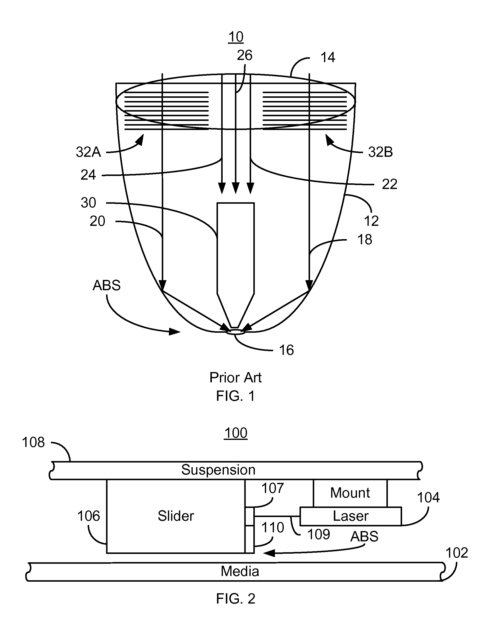
[0015]FIG. 2 is a diagram depicting a portion of an EAMR disk drive 100. For clarity, FIG. 2 is not to scale. For simplicity not all portions of the EAMR disk drive 100 are shown. In addition, although the disk drive 100 is depicted in the context of particular components other and / or different components may be used. Further, the arrangement of components may vary in different embodiments. The EAMR disk drive 100 includes media 102, a laser 104, a slider 106, one or more gratings 107, suspension 108, and an EAMR transducer110. In some embodiments, the laser 104 is a laser diode. The EAMR transducer 110 is coupled with the laser 104. In one embodiment, the EAMR transducer is optically coupled to the laser 104 through the grating 107. Thus, line 109 represents electromagnetic energy (light) provided from the laser 104 to the grating(s) 107. In addition, although the laser 104 is shown as separately mounted to the suspension 108, in other embodiments, the laser 104 may be mounted else...


PUM

PropertyMeasurementUnit
widthaaaaaaaaaa
diameteraaaaaaaaaa
diameteraaaaaaaaaa

Abstract

A method and system for providing an energy assisted magnetic recording (EAMR) transducer coupled with a laser are described. The EAMR transducer has an air-bearing surface (ABS) configured to reside in proximity to a media during use. The method and system include providing at least one waveguide, at least one write pole, and at least one coil. The waveguide(s) are for directing the energy from the laser toward the ABS. The write pole(s) each include a write pole tip, a yoke, a back pedestal and a return pole. The write pole tip is coupled to the back pedestal through the yoke. The back pedestal has at least one aperture therein. The aperture(s) are configured to allow the energy from the laser to pass therethrough. The coil(s) are for energizing the at least one write pole.

Description

BACKGROUND[0001]FIG. 1 depicts a portion of a conventional energy assisted magnetic recording (EAMR) transducer 10. The conventional EAMR transducer 10 is used in writing a recording media (not shown in FIG. 1) and receives light, or energy, from a conventional laser (not shown in FIG. 1). The conventional EAMR transducer 10 includes gratings 32A and 32B, a conventional waveguide 12, and conventional pole 30. The conventional EAMR transducer 10 is shown with a laser spot 14 that is guided by the conventional waveguide 12 to a smaller spot 16 near the air-bearing surface (ABS) and thus the media (not shown). Other components that may be part of the conventional EAMR transducer 10 are not shown.[0002]In operation, light from the spot 14 is coupled to the conventional EAMR transducer 10 using the gratings 32A and 32B. The waveguide 12, which is shown as a planar solid immersion mirror, directs light from the gratings 32A and 32B to the spot 16. In other conventional EAMR transducers, t...

Claims


Application Information

Patent Timeline
Patent Type & Authority Patents(United States)
IPC IPC(8): G11B11/00
CPCG11B5/105G11B5/1278G11B5/314G11B5/6088G11B2005/0021
Inventor HU, YUFENGWANG, YUGANG
Owner WESTERN DIGITAL TECH INC
Why Eureka
Try Eureka