
Floor panel, flooring system and method for laying flooring system

a flooring system and flooring technology, applied in the field of flooring systems and methods for laying flooring systems, can solve the problems of difficult installation of flooring panels, easy separation of tongue-and-groove joints, and disassembly of flooring installation, and achieve the effect of easy installation

Active Publication Date: 2012-10-09
YEKALON IND
View PDF27 Cites 112 Cited by
  • Summary
  • Abstract
  • Description
  • Claims
  • Application Information

AI Technical Summary

Benefits of technology

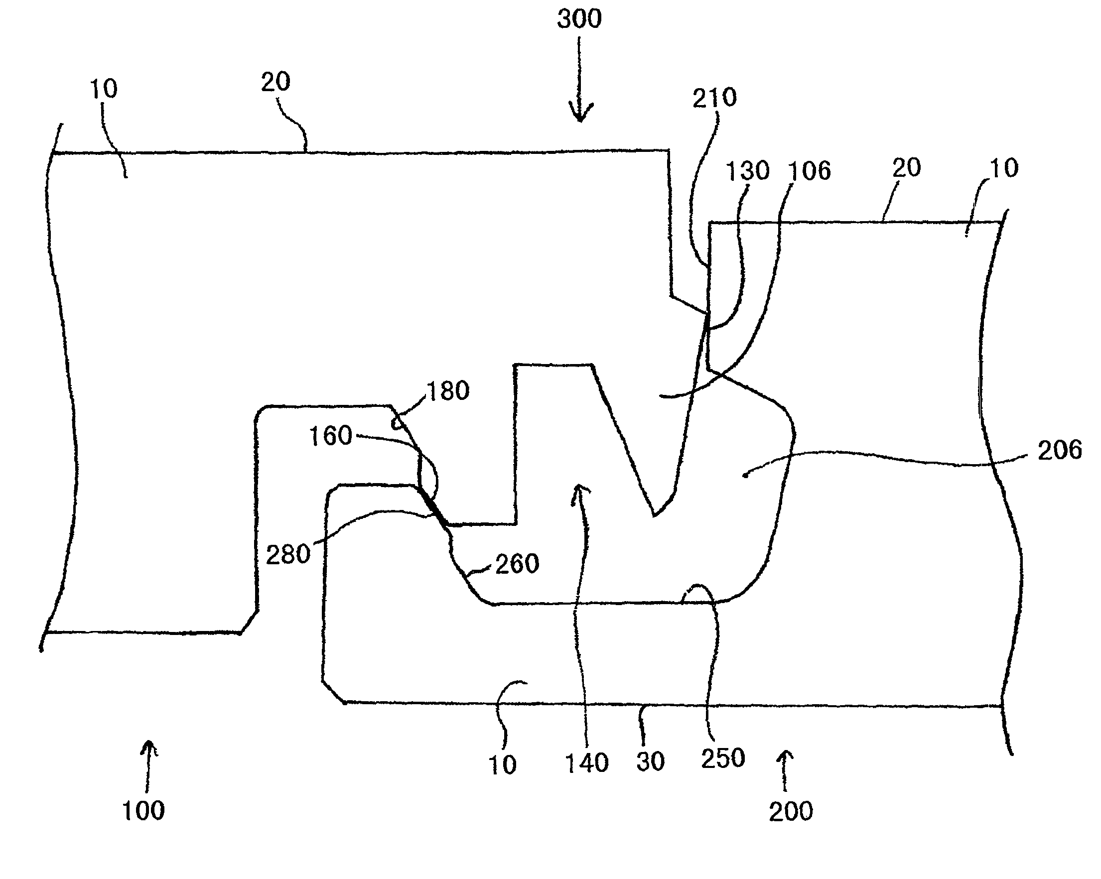
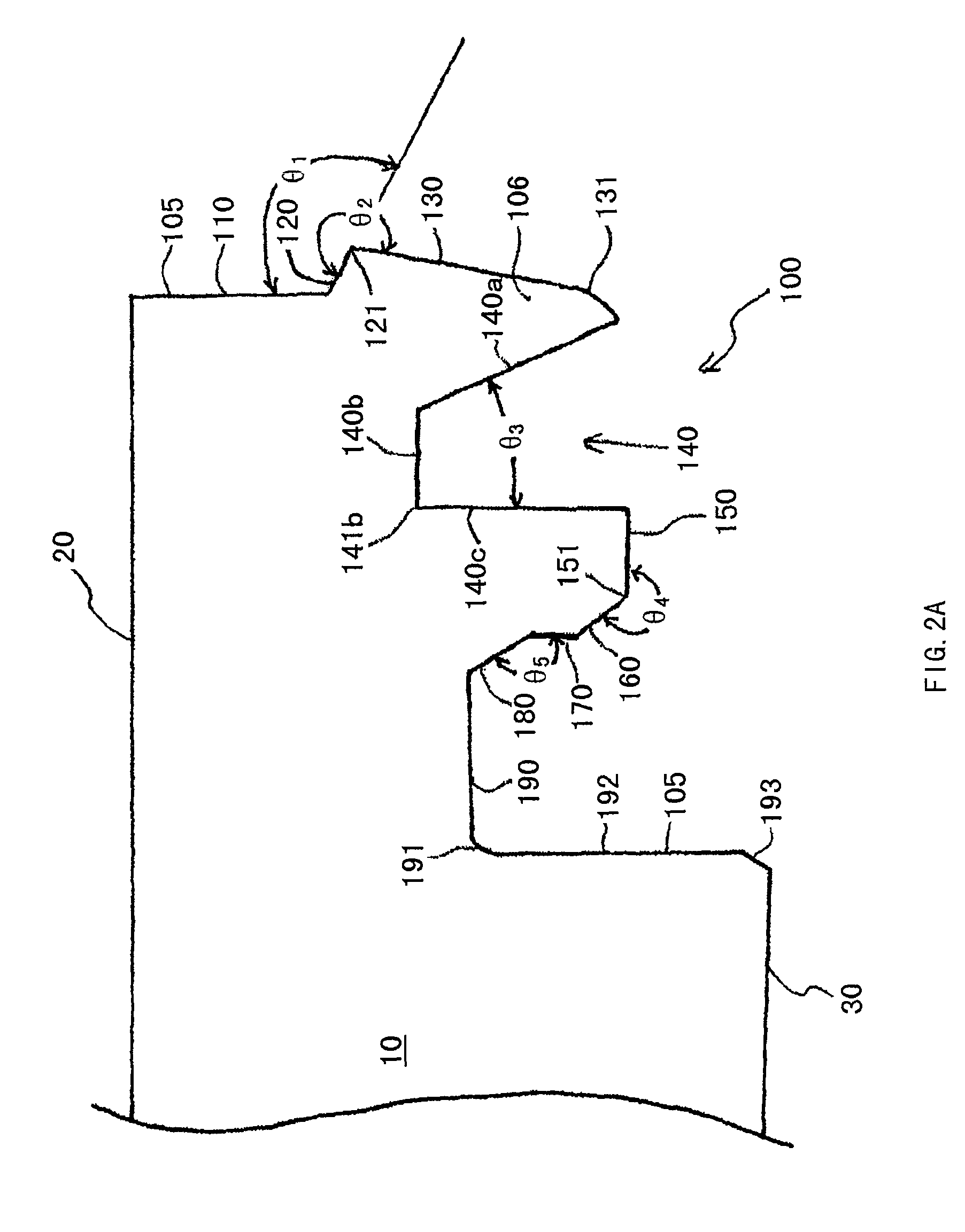
[0005]An object of the present invention is to provide a novel “protrusion-recess” structure which not only ensures transverse connection and horizontal locking between a protrusion and a recess but also is installed very easily even at a corner of wall, without decoupling.
[0013]As to flooring system, a flooring system includes a first floor panel and a second floor panel, the first floor panel comprising: an upper surface; a floor contact surface; a recess end face including: (1) an upper lip adjacent to the upper surface, (2) a lower lip and (3) a recess including a upper first contact surface, a lower second contact surface and a guide surface; the second floor panel including: an upper surface; a floor contact surface; and a protrusion end face, the protrusion of which including a upper first contact surface, a lower second contact surface and a guide surface. When the protrusion of one floor panel is placed in the recess of another identical floor panel and a pressure is applied thereto in a direction substantially perpendicular to the upper surface, the pressure makes the protrusion guide surface in contact with the recess guide surface and introduces the protrusion into the recess. And, when the protrusion end face and the recess end face of an identical one of the panel are coupled, the upper protrusion first contact surface engages the upper recess first contact surface to prevent decoupling of the panel in a direction perpendicular to the plane of the upper surface, and the lower protrusion second contact surface engages the lower recess second contact surface to prevent decoupling of the panel in a direction perpendicular to the protrusion end face.

Problems solved by technology

While this provides for easy installation, it also renders the tongue-and-groove joint susceptible to separation by physical or temperature-dependent disturbance of the flooring.
Separation is undesirable because it can cause a flooring installation to become disassembled and because it is aesthetically displeasing.
While such a design can overcome much of the susceptibility to separating, these flooring panels can be difficult to install.

Method used


Image

  • Floor panel, flooring system and method for laying flooring system
  • Floor panel, flooring system and method for laying flooring system
  • Floor panel, flooring system and method for laying flooring system

Examples


Embodiment Construction

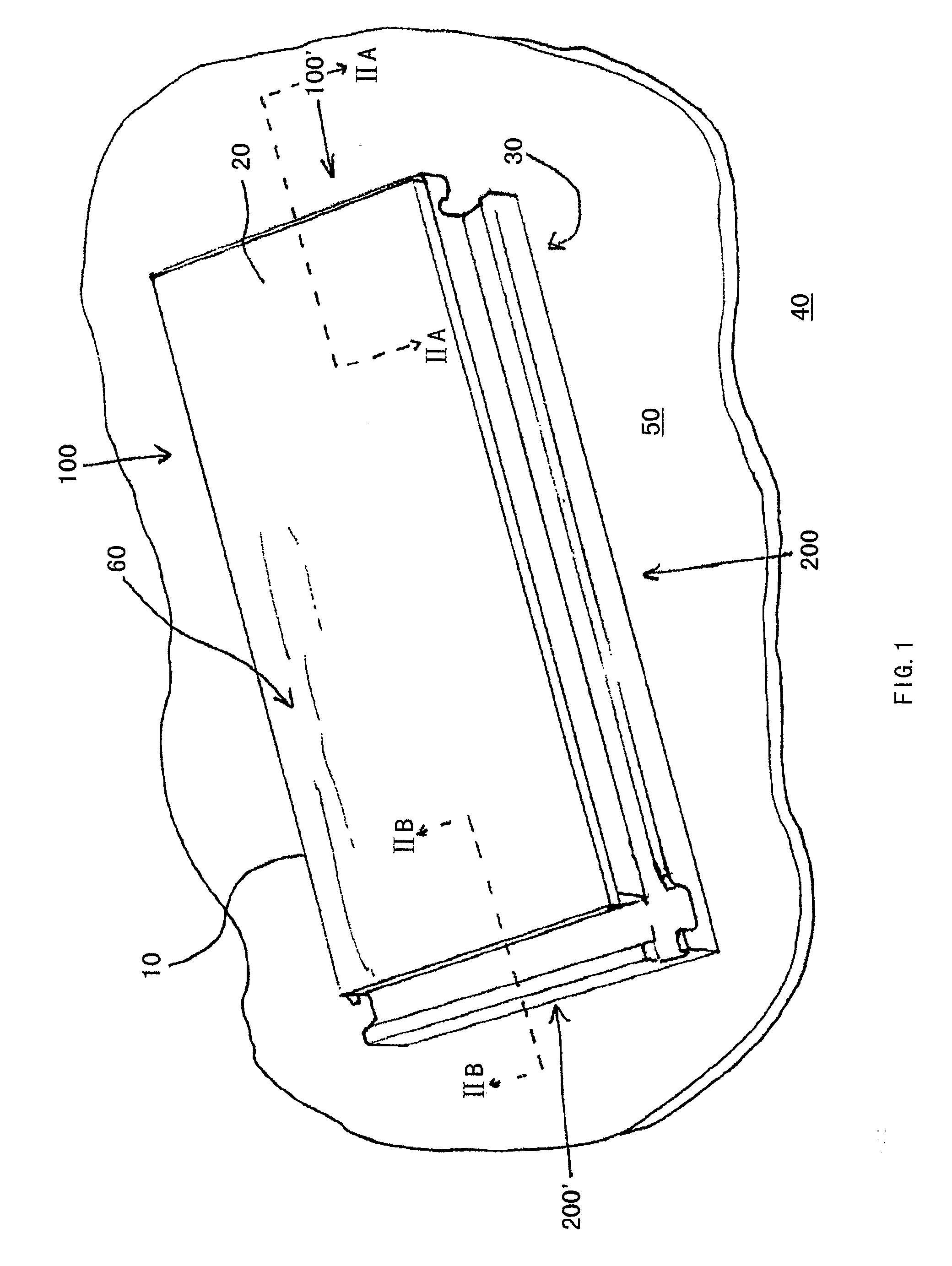
[0031]In general, referring to FIG. 1, a floor panel 10 has an upper surface and a floor contact surface 30 which preferably are generally disposed in parallel planes. When the floor panel is installed, the floor contact surface 30 contacts the floor 40 upon which the panel is installed, or an underlayment such as a foam underlayment 50, which optionally may be installed between the floor 40 and the floor panel 10. When floor panel 10 is installed, upper surface 20 is visible. Upper surface 20 may include a decoration 60 which is visible when panel 10 is installed.

[0032]Decoration 60 can be a simulated wood grain, or any other known decoration. For example, decoration 60 can depict a stone surface. Decoration 60 can include a laminated decoration, and can be formed by any known method, such as laminating a photograph of a wood grain between panel 10 and a plastic coating. Decoration 60 can also include an amount of material such as wood. For example, decoration 60 can be a wood vene...


PUM


Abstract

A floor panel comprises a protrusion end face having a protrusion and a recess end face having a recess. The profiles of the protrusion and the recess are allowed to be installed in the following manner: placing the protrusion nearby the recess of an already installed floor panel, and then applying a pressure to introduce the protrusion in the recess. A flooring system allows use of said method to install more than one floor panel. According to the solution of the present invention, the installation and pave of the floor panels is very simple and the installed floor panels do not easily separate.

Description

CROSS-REFERENCE TO RELATED APPLICATIONS[0001]This application claims priority to PCT / CN2006 / 000684, filed Apr. 14, 2006.TECHNICAL FIELD[0002]The present invention relates to a floor panel, a flooring system formed by multiple floor panels and a method for laying the floor panels.BACKGROUND TECHNOLOGY[0003]Hardwood has been used as a floor covering for several hundred years, and both hardwood floor and wood composite laminate flooring have utilized a conventional tongue-and-groove coupling. In the traditional “tongue-and-groove” structure, a tongue and corresponding groove can be easily coupled by laterally shifting the tongue towards a groove in the same plane. While this provides for easy installation, it also renders the tongue-and-groove joint susceptible to separation by physical or temperature-dependent disturbance of the flooring. Separation is undesirable because it can cause a flooring installation to become disassembled and because it is aesthetically displeasing.[0004]Tong...

Claims


Application Information

Patent Timeline
Patent Type & Authority Patents(United States)
IPC IPC(8): E04B1/00
CPCE04F15/02E04F15/04E04F2201/041E04F2201/0153E04F2201/03E04F2201/0138E04F15/02038E04F2201/043E04F2201/027
Inventor DU, YONGSHENG
Owner YEKALON IND
Learn More