Wave gear device
a gear device and wave technology, applied in the direction of gearing, hoisting equipment, slip coupling, etc., can solve the problems of abnormal abrasion, increased vibration, and reduced ratcheting torque of the two gears, so as to prevent the formation of plastic deformation in the tooth portion or the lik
- Summary
- Abstract
- Description
- Claims
- Application Information
AI Technical Summary
Benefits of technology
Problems solved by technology
Method used
Image

Examples
embodiment 1
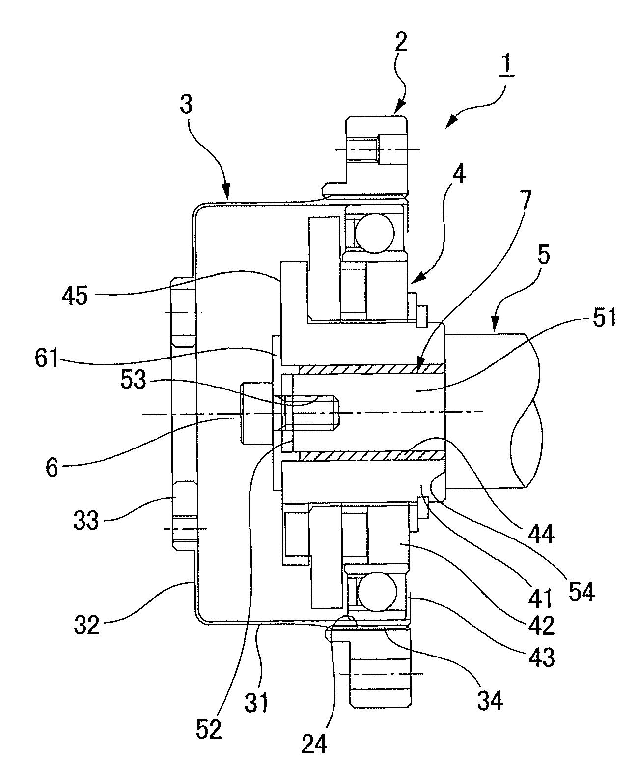
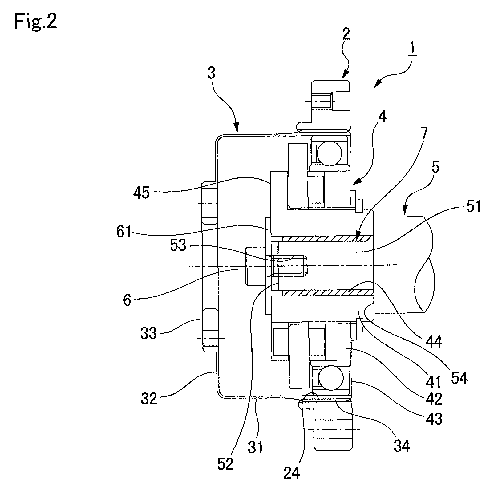
[0039]FIG. 2 is a schematic longitudinal sectional view that shows a cup-type wave gear device to which the present invention has been applied. A wave gear device 1 has an annular rigid internally toothed gear 2, a cup-shaped flexible externally toothed gear 3 coaxially disposed inside the rigid internally toothed gear, and a wave generator 4 having an elliptical profile fitted inside the flexible externally toothed gear 3. The wave generator 4 elliptically flexes the flexible externally toothed gear, and external teeth 34 of the two end portions of the major axis thereof are made to mesh with internal teeth 24 of the rigid internally toothed gear 2.
[0040]A motor shaft or another rotating input shaft 5 is coaxially connected and secured to the wave generator 4. When the wave generator 4 is rotated by the rotating input shaft 5, the meshing location of the two gears 2, 3 moves in the circumferential direction, and the two gears rotate relative to each other in correspondence with the...
embodiment 2
[0046]FIG. 3 is a schematic longitudinal sectional view that shows the wave gear device of embodiment 2 to which the present invention has been applied. Since the essential composition of the wave gear device 1A is the same as that of the wave gear device 1 of embodiment 1, the same reference numerals are used for the corresponding locations, and a description thereof is omitted.
[0047]In the wave gear device 1A of embodiment 2, the small-diameter shaft end portion 51 of the rotating input shaft 5 is directly press-fitted without an interposed friction ring to a center through-hole 44 of the cylinder hub 41 and secured to the cylinder hub 41 with the aid of the fastening bolt 6.
[0048]A friction disc 7A provided with a center-hole is sandwiched between the annular step surface 54 of the rotating input shaft 5 and the shaft end surface 46 of the cylinder hub 41 that faces the annular step surface. The friction coefficient of the friction disc 7A and the tightening force in the radial d...
PUM
 Abstract
Description
Claims
Application Information
 - R&D Engineer
- R&D Manager
- IP Professional
- Industry Leading Data Capabilities
- Powerful AI technology
- Patent DNA Extraction
Browse by: Latest US Patents, China's latest patents, Technical Efficacy Thesaurus, Application Domain, Technology Topic.
© 2024 PatSnap. All rights reserved.Legal|Privacy policy|Modern Slavery Act Transparency Statement|Sitemap