Shipping and display tray with article support

a technology of article support and packaging, applied in the field of packaging and display containers, can solve the problems of increasing the time to assemble and the cost of the overall package, and achieve the effect of increasing the efficiency of set-up tim

Active Publication Date: 2012-10-09
INT PAPER CO
View PDF20 Cites 10 Cited by
  • Summary
  • Abstract
  • Description
  • Claims
  • Application Information

AI Technical Summary

Benefits of technology

[0009]Some of the advantages of the present invention shipping and display tray is to: 1) provide a printed surface on inside side walls of the assembled tray 2) have a sidewall height that would help to support and stabilize the blister cards used inside which the blister cards and the side walls are the same height 3) hold the blister cards in place by using bumpers or air cells 4) increase efficiencies in set-up time 5) display product fully from front and provide easy removal and possible replacement of product 6) creates sidewalls that slope back or tapered downwardly to maximize visual exposure of the blister cards in front and 7) reduce square footage of cardboard used.
[0010]Other advantages of the present invention are: 1) Reduced labor in set up time due to pre-glued bumpers. No prior known holding display trays currently incorporate this feature. Other holding display trays use several parts to accomplish the same requirements. This increases time to assemble and also the cost of the overall package. 2) Option of using a unique “pop-up” front tab that allows the blister cards to be held with two shorter width bumpers. These two shorter width bumpers enable the blister cards to position product lower to the bottom and increase product contained or improve billboard effect of smaller sized blisters. Pop-up front tab is an optional feature. 3) Optional locking tabs in the two shorter width bumpers were also developed to provide a more positive locking mechanism during assembly. 4) When looking at this display tray from a marketing standpoint, it provides several areas that can be utilized as printed surfaces when conventional printing techniques are used. Printing on the outside of the sheet provides all areas of the assembled structure (except the back inside) with printed areas. This helps to increase market driven solutions through graphics.
[0011]Accordingly, one aspect of the present invention is directed to a shipping and display tray for holding a plurality of articles contained therein in an upright position at a point of sale. The shipping and display tray is made of paperboard and defined by a one-piece shallow tray having a bottom wall, a front wall, a back wall, and opposite side walls foldably joined with one another. A plurality of parallel spaced apart bumpers are foldably joined to the respective opposite side walls and forming two rows, an aisle, and a plurality of channels when positioned on the bottom wall. The plurality of the channels engages with bottom edges of the plurality of articles to hold the article in standing upright position and prevent the articles from falling over when one of the articles is removed from the display tray. The front wall of the tray includes a flap panel foldably joined thereto and has a pair of openings used to engage with the bumpers. Two of the plurality of bumpers each of which has a tab that is inserted into the respective openings. The front wall also includes a pop-up front used to enhance surface area of the front wall for printing indicia.
[0012]Another aspect of the present invention is directed to a shipping and display tray for holding a plurality of articles contained therein in an upright position at a point of sale. The shipping and display tray is made of paperboard and defined by a one-piece shallow tray having a bottom wall, a front wall having a flap panel foldably joined thereto, a back wall, and opposite side walls foldably joined with the flap panel. The bottom wall contains a plurality of parallel spaced apart bumpers having at least one row and a plurality of channels used to engage with bottom edges of the plurality of articles to hold the article in standing upright position and prevent the articles from falling over when one of the articles is removed from the display tray.

Problems solved by technology

No prior known holding display trays currently incorporate this feature.
This increases time to assemble and also the cost of the overall package.

Method used


Image

  • Shipping and display tray with article support
  • Shipping and display tray with article support
  • Shipping and display tray with article support

Examples


Embodiment Construction

[0022]While this invention is susceptible of embodiment in many different forms, there is shown in the drawings and will herein be described in detail preferred embodiments of the invention with the understanding that the present disclosure is to be considered as an exemplification of the principles of the invention and is not intended to limit the broad aspect of the invention to the embodiments illustrated. In the present invention the use of prime character in the numeral references in the drawings directed to the different embodiment indicate that those elements are either the same or at least function the same or those elements are in the unfolded position.

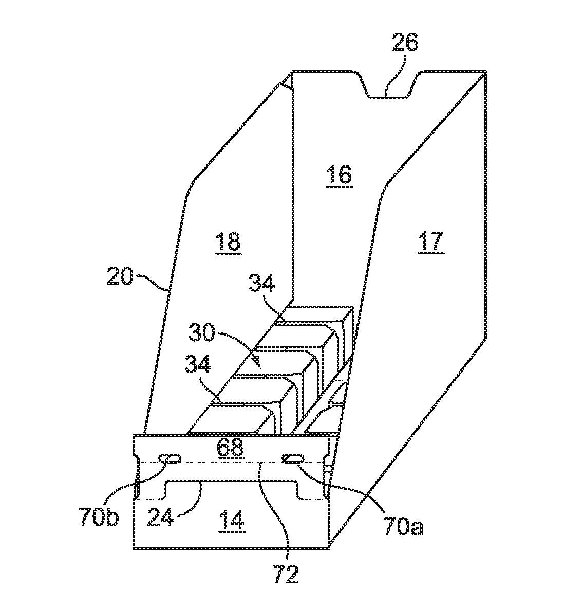
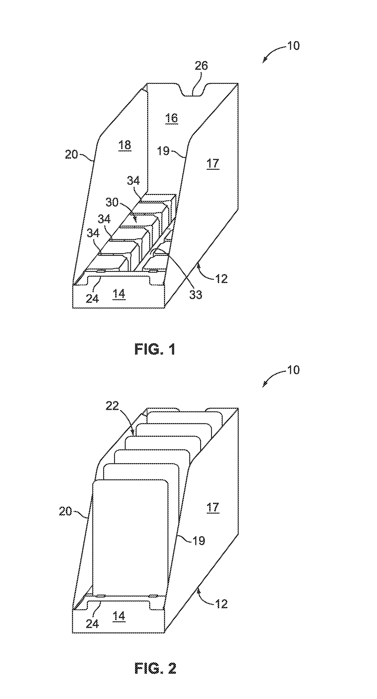
[0023]FIG. 1 is a top perspective view of a shipping and display tray 10 according to the invention. The display tray 10 includes a bottom wall 12, front wall 14, back wall 16, and opposite side walls 17 and 18. In the particular example shown, the front wall 14 has much less height than the back wall 16 and the upper edges 1...


PUM


Abstract

The present invention is directed to a shipping and display tray for holding a plurality of articles contained therein in an upright position at a point of sale. The shipping and display tray is made of paperboard and defined by a one-piece shallow tray having a bottom wall, a front wall, a back wall, and opposite side walls foldably joined with one another. A plurality of parallel spaced apart bumpers are foldably joined to the respective opposite side walls and forming two rows, an aisle, and a plurality of channels when positioned on the bottom wall. The plurality of the channels engages with bottom edges of the plurality of articles to hold the article in standing upright position and prevent the articles from falling over when one of the articles is removed from the display tray. The front wall of the tray includes a flap panel foldably joined thereto and has a pair of openings used to engage with the bumpers.

Description

CROSS REFERENCE TO RELATED APPLICATION[0001]This application claims priority to U.S. provisional patent application Ser. No. 61 / 366,975, filed on 23 Jul. 2010, which is hereby incorporated hereunto by reference as if fully restated herein.FIELD OF THE INVENTION[0002]This invention relates generally to a shipping and display container, constructed from a unitary paperboard blank for holding a plurality of articles and more particularly, to a shipping and display tray having a plurality of bumpers and a locking feature and is easily assembled and reduces the amount of paperboard typically used in similar packages.BACKGROUND OF THE INVENTION[0003]Many products for sale to the public are placed in a primary package that is designed for display at the point of sale. One common practice is to place a quantity of the primary packages in a secondary container for shipping. The retailer must then remove the primary packages from the secondary container and hang them from a hook or place them...

Claims


Application Information

Patent Timeline
Patent Type & Authority Patents(United States)
IPC IPC(8): B65D79/00
CPCB65D5/5021
Inventor SMITH, JEFFREY A.
Owner INT PAPER CO
Why Eureka
Try Eureka