Ball sleeve joint and process for manufacturing same

a technology of ball sleeves and manufacturing processes, applied in the field of sleeves, can solve the problems of ball sleeves, ball sleeves, ball shell failure, etc., and achieve the effects of reducing manufacturing process costs, reducing service life, and reducing manufacturing costs of such joints

Active Publication Date: 2012-10-09
ZF FRIEDRICHSHAFEN AG
View PDF7 Cites 23 Cited by
  • Summary
  • Abstract
  • Description
  • Claims
  • Application Information

AI Technical Summary

Benefits of technology

[0006]Based on the described drawbacks of ball sleeve joints known from the state of the art, the object according to the present invention is to improve a ball sleeve joint of the type of this class such that its service life is considerably increased compared to prior-art embodiments, and the manufacturing costs of such a joint can also be estimated to be low at the same time. Moreover, compensation of tolerances in the dimensions, especially between the bearing shell and the joint housing, shall be brought about by suitable measures with simple means, because the manufacturing process costs can be significantly lowered in case of a broader range of the usually narrow tolerance values of ball sleeve joints.
[0012]The application of the pressing forces to the housing halves is a possibility that can be embodied in a technologically simple manner to bring about, in conjunction with the elastic properties of the bearing shell, a compensation of the dimensional tolerances of the components mounted with one another, and the defined pressing forces guarantee increased stiffness of the joint due to the prestress, which is controlled in terms of force, as a consequence of the pressing together of the bearing shell halves.
[0013]The force-controlled prestress can be embodied with small dispersion tolerances. Moreover, it is guaranteed that no additional external forces will act on the bearing shell due to the subsequent connection in substance, unlike, for example, in case of fixation of the bearing shell by means of closing rings fixed by rolling. The connection in substance itself, be it brought about by a welding operation, a soldering operating or a bonding operation, can be embodied at low cost because of the general technical conditions and the currently common devices, so that the manufacturing costs are, on the whole, markedly lower than was hitherto usual as a consequence of the process according to the present invention.
[0014]Special embodiments of both the ball sleeve joint according to the present invention are discussed below. It proved to be especially advantageous concerning the ball sleeve joint to prepare the connection in substance as a welding. Tempering of the joint can be achieved by the heat supplied during the welding process, as a result of which a better contact pattern is generated in the joint and a subsequent settling of the bearing shell is prevented from occurring.
[0017]Embodying the welded connection as a laser weld is advantageous especially due to the fact that laser welding is a low-cost and accurate possibility of establishing the welded connection.

Problems solved by technology

The POM plastic material, which is preferably used here, has the drawback that the plastic material begins to creep under increased load and migrates into the slots present in the bearing shell.
Increased clearance, which leads to failure of the entire component within a short period of time, will develop in the ball sleeve joint as a result.
This drawback is additionally supported by the fact that the joint closure must also be considered to be relatively elastic, especially in case of one-part ball sleeve joints, due to closing rings designed as sheet metal parts, and the ball shell, fixed by the closing rings, cannot be sufficiently supported in case of a correspondingly increased load.

Method used


Image

  • Ball sleeve joint and process for manufacturing same
  • Ball sleeve joint and process for manufacturing same
  • Ball sleeve joint and process for manufacturing same

Examples


Embodiment Construction

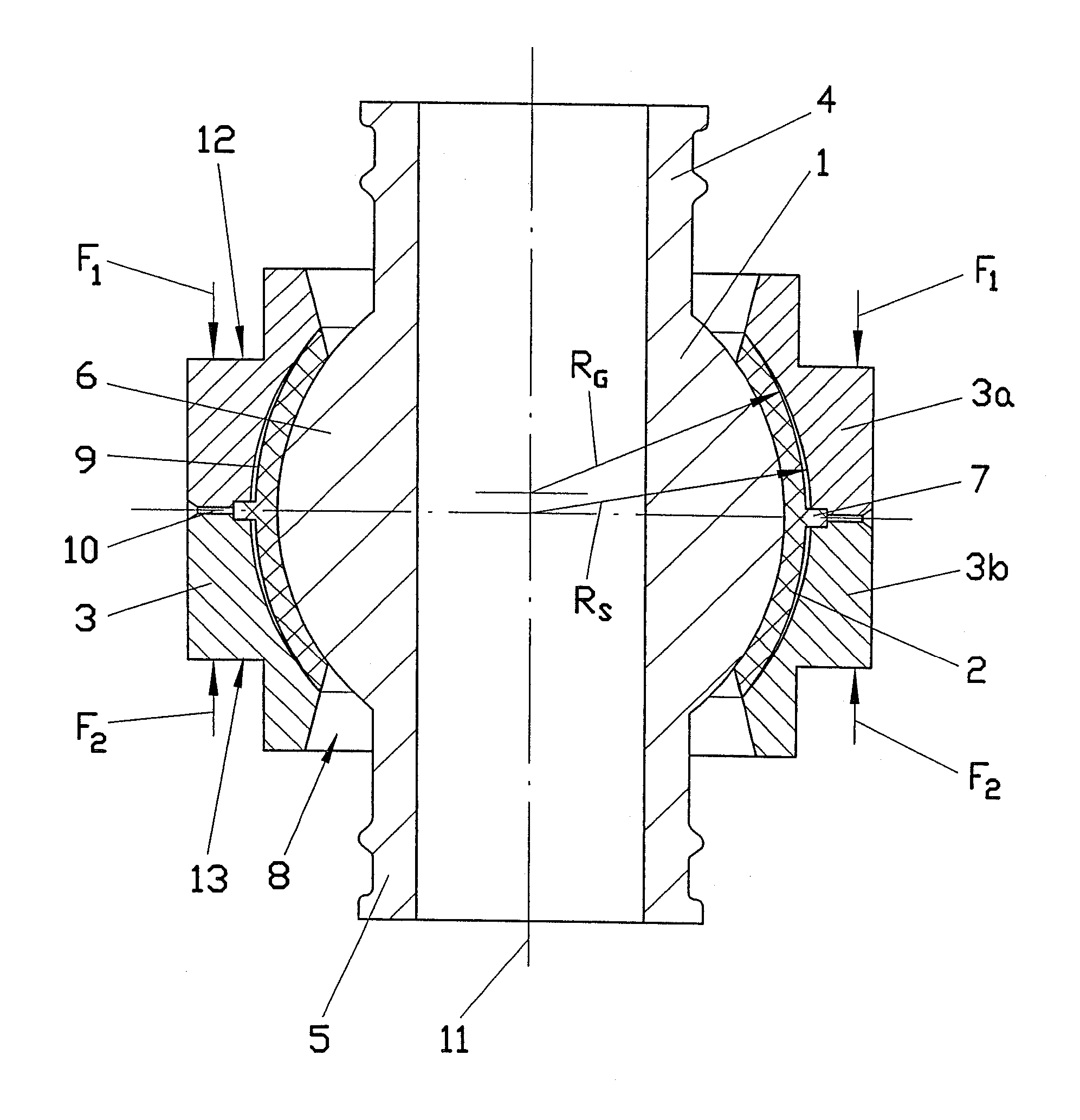
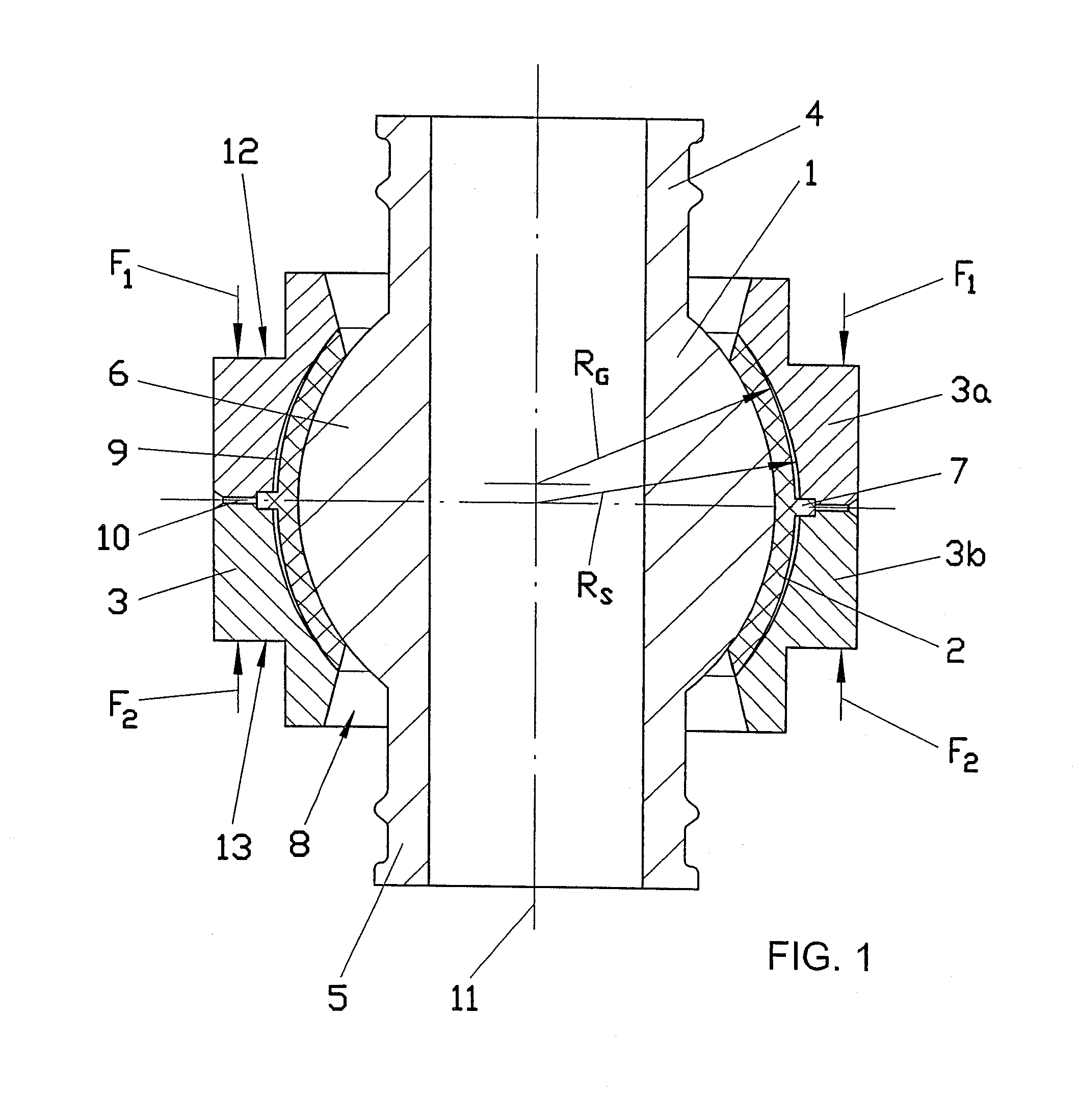
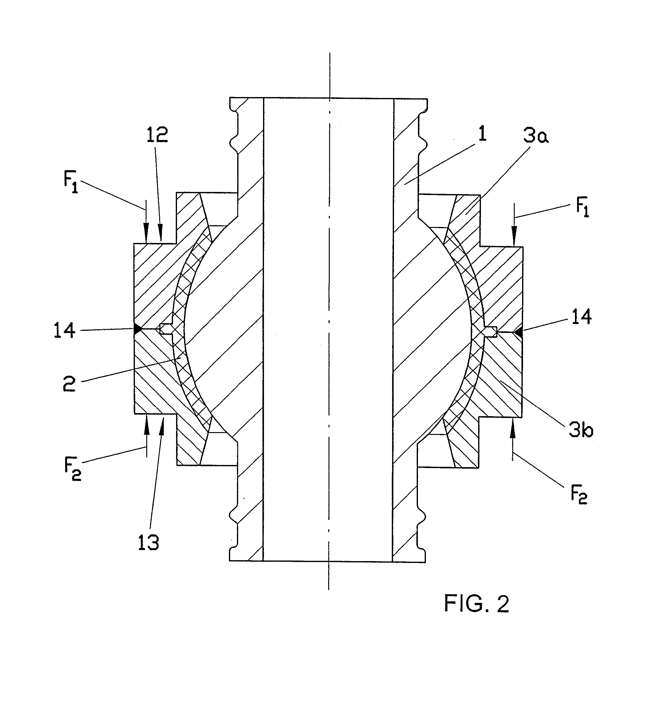
[0024]Referring to the drawings in particular, the ball sleeve joint according to the present invention, which is shown in two different embodiment variants in FIGS. 1 through 3, comprises essentially a ball sleeve 1, which is provided with a through hole, a bearing shell 2 as well as a joint housing 3, which surrounds the bearing shell and is composed of two essentially symmetrically shaped housing halves (parts) 3a and 3b.

[0025]The ball sleeve 1 has two symmetrical end areas 4, 5 as well as a middle area, which is located between them and which is shaped as a spherical bearing surface 6 on its outer contour, but other embodiments, such as ovally shaped bearing surfaces, are conceivable as well. The bearing surface 6 is surrounded by the bearing shell 2, which likewise has a spherical shape corresponding to the contour of the bearing surface 6 and has an essentially constant thickness over its cross section in this exemplary embodiment. A holding projection 7, which is designed as...


PUM


Abstract

A ball sleeve joint is provided, especially for chassis assembly units and steering assembly units of motor vehicles. The ball sleeve joint includes a joint housing with two housing halves and a ball sleeve provided with a rounded bearing surface. The bearing surface is accommodated in a joint housing, which is manufactured from an elastic plastic and is fixed in a recess of the joint housing, as well as a process for manufacturing such a ball sleeve joint. The two housing halves (3a, 3b) are pressed together with defined pressing forces during the mounting of the ball sleeve joint (1) in the direction of the longitudinal axis of the ball sleeve joint (1). The two housing parts are held in the installed position predetermined by the pressing forces by means of at least one connection (14) in substance between the housing parts (3a, 3b).

Description

CROSS REFERENCE TO RELATED APPLICATIONS[0001]This application is a United States National Phase application of International Application PCT / DE2005 / 001394 and claims the benefit of priority under 35 U.S.C. §119 of German Patent Application DE 10 2004 040 412.7 filed Aug. 19, 2004, the entire contents of which are incorporated herein by reference.FIELD OF THE INVENTION[0002]The present invention pertains to sleeve joint especially for chassis assembly units and steering assembly units of motor vehicles and more particularly to a joint with a joint housing comprising two housing parts and a ball sleeve provided with a rounded bearing surface, wherein said bearing surface is accommodated in a bearing shell, which is manufactured from an elastic plastic and is fixed in a recess of the joint housing. The invention further relates to a process for preparing such a ball sleeve joint.BACKGROUND OF THE INVENTION[0003]Ball sleeve joints are known, in principle, in the state of the art and are...

Claims


Application Information

Patent Timeline
Patent Type & Authority Patents(United States)
IPC IPC(8): F16C11/00F16C23/04
CPCF16C11/0614F16C23/046Y10T403/32704Y10T403/32786Y10T403/32737Y10T403/32803Y10T403/32713Y10T403/32795F16C11/06
Inventor RECHTIEN, MARTINGRUBE, VOLKER
Owner ZF FRIEDRICHSHAFEN AG
Why Eureka
Try Eureka