Filter device with a heater

a filter device and heater technology, applied in the direction of filtration separation, machine/engine, separation process, etc., to achieve the effect of uniform distribution of thermal energy supplied, small installation space and localization

Active Publication Date: 2012-10-09
ROBERT BOSCH GMBH
View PDF71 Cites 17 Cited by
  • Summary
  • Abstract
  • Description
  • Claims
  • Application Information

AI Technical Summary

Benefits of technology

[0006]In contrast to known filter devices, which are provided with PTC elements as heaters, according to the invention, for heating the filter device, a heating track or heating wire or even a heating coil is provided that is also injection-molded into the filter housing of the filter device. With this kind of injection molding, also known as insert-molding, the heating track provided according to the invention can be integrated, during the production of the filter housing, with the wall of the filter housing at comparatively little effort and expense. Accordingly, the logistical effort and expense known from the prior art as well as the assembly effort and expense for a heating element are dispensed with. The heating track of the invention is especially advantageously embodied as a stamped grating, which in a manner similar to known conductor tracks is stamped out by a stamping process from a striplike or sheetlike piece of sheet metal. The stamped grating (especially in the grid portions separate from the actual heater) may also include further electrical functions, such as supplying current to the associated filter device or diverting current from it. The injection-molding process to be provided can build on extensive knowledge and experience with other components that in the most various kinds of technical equipment are now being injection-molded into housings made in particular from plastic. A further advantage of the invention is considered to be that the medium flowing through the filter device, while in the interior of the filter housing it is in the immediate vicinity of the heater, nevertheless does not come into direct contact with the heater. This kind of direct contact is a problem in known filter devices, for instance in filtering a solution of urea and water, since urea already decomposes at approximately 60° C.
[0007]It is furthermore an important advantage of the heater of the invention that this heater leads to especially uniform distribution of the thermal energy supplied, beyond the surface area of the heater itself. As a result, local (harmful or unwanted) temperature peaks at the filter housing are avoided. At the same time, the heater of the invention and thus the entire filter device requires especially little installation space, with at the same time high heating output. In particular, the temperature sought in all the essential filter regions is attained quite quickly and largely uniformly.
[0008]To create a filter that can be used especially expediently particularly for automotive applications and at the same time to achieve high efficiency of the heater of the invention, it is advantageous to embody the filter housing cylindrically, and to locate the at least one heating track in the jacket portion of the cylindrical filter housing.
[0009]The aforementioned advantages with regard to especially good utilization of the heating energy supplied and the creation of an especially demand-responsive temperature profile beyond the surface of the filter housing of the invention can moreover be attained to a particular extent by providing that the at least one heating track is distributed in looplike fashion in the surface of the filter housing.
[0010]Alternatively or in addition, the effort and expense for assembly of the filter device of the invention can be kept especially low if the at least one heating track is not injection-molded directly into the filter housing, but instead if it is pre-positioned in a retaining element. With the retaining element, the individual loops of the heating track can be retained relative to one another and in relationship to connection contacts in a defined way. The heating tracks thus retained can then be easily further processed and can for instance also be automatically delivered to an injection molding machine that is provided for injection-molding the heating tracks into the filter housing. The retaining element itself may have been created in an injection-molding process, in which the heating track in particular has been put in place and insert-molded. This insert-molding can be done with injection-molding machines that are arranged especially for the (small-area) insert-molding of the heating track, while injection-molding machines for producing the housing must as a rule meet considerably more-complex demands, for instance with regard to the surface quality of the filter housing produced.
[0011]To attain an especially good heat input, fast reaction capability, and high efficiency, it is also advantageous in the filter device of the invention if the at least one heating track is located essentially on the inside of the filter housing. In this arrangement, the heating track is only slightly covered with material comprising the filter housing.

Problems solved by technology

This kind of direct contact is a problem in known filter devices, for instance in filtering a solution of urea and water, since urea already decomposes at approximately 60° C.

Method used


Image

  • Filter device with a heater
  • Filter device with a heater
  • Filter device with a heater

Examples


Embodiment Construction

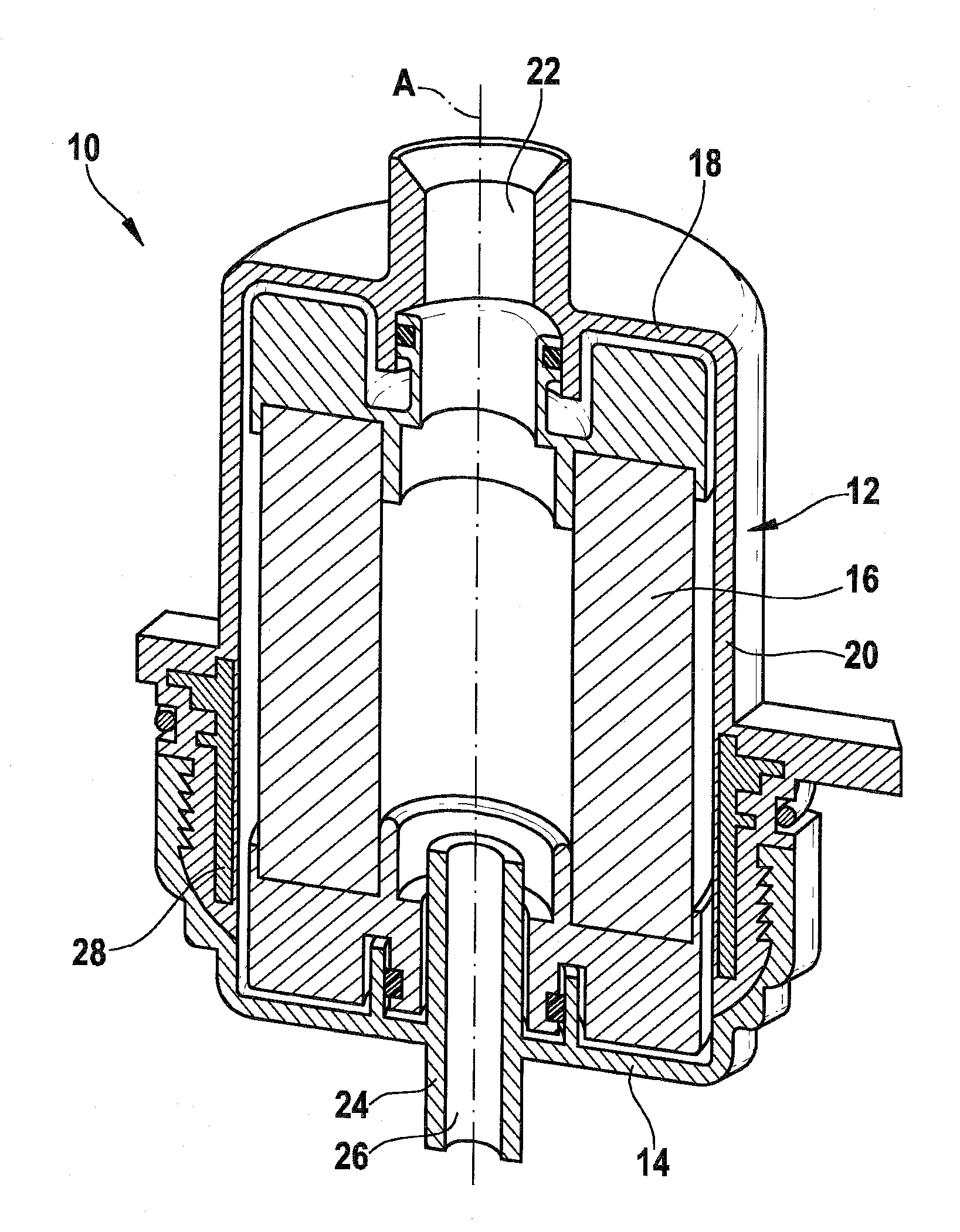
[0030]In the drawings, a filter device 10 is shown, which as its fundamental elements has a filter housing, composed of a housing cup 12 and a housing cap 14, and a filter element 16 located in the filter housing.

[0031]The housing cup 12 is embodied in its basic shape as a cup, which includes a housing bottom 18 and an annular wall 20 adjoining it on the circumference. The annular wall 20 is embodied essentially cylindrically about a longitudinal axis A. The housing bottom 18 is penetrated centrally by a through opening 22, which is used for connecting a sensor, not shown. Diametrically opposite in the housing cap 14, a mandrel 24 is embodied, with a through opening 26 penetrating it in the direction of the longitudinal axis A.

[0032]In operation of the filter device 10, a fluid or medium, such as fuel or urea, is introduced through this through opening 26 and subsequently passes from radially inside radially outward through the filter element 16 and leaves the filter device 10 throu...


PUM

PropertyMeasurementUnit
impedanceaaaaaaaaaa
thermally conductiveaaaaaaaaaa
electrical energyaaaaaaaaaa

Abstract

Disclosed is a filter device (10), particularly a liquid filter, comprising a filter element (16) that is disposed in a filter housing (12, 14) and a heater (28) for heating medium flowing through the filter device (10). The inventive filter device (10) is characterized in that the heater (28) is designed with at least one heating circuit (30) that is molded into the filter housing (12, 14). Alternatively or additionally, the heater (28) is designed with at least one heating circuit (30) which is provided with an electrical contact (34) in at least one of the final zones thereof, said electrical contact (34) being riveted to the heating circuit (28).

Description

CROSS-REFERENCE[0001]The invention described and claimed hereinbelow is also described in PCT / EP2006 / 064837, filed on Jul. 31, 2006, DE 10 2005 038 536.2, filed Aug. 16, 2005 and DE 10 2006 034 077.9, filed Jul. 24, 2006. These German Patent Applications, whose subject matter is incorporated here by reference, provide the basis for a claim of priority of invention under 35 U.S.C. 119 (a)-(d).BACKGROUND OF THE INVENTION[0002]The invention relates to a filter device, in particular a fluid filter, such as a urea filter or fuel filter, having a filter element that is disposed in a filter housing, and having a heater for heating a medium flowing through the filter device.[0003]In filter devices and in particular in fluid filters under various operating conditions, to ensure uniformly good filtration, it is known to provide a heater on each of the filter devices. With the heater, freezing or flaking of the filtrate, for instance, such as diesel fuel, in cold starting of an associated moto...

Claims


Application Information

Patent Timeline
Patent Type & Authority Patents(United States)
IPC IPC(8): B01D35/18F02M37/22
CPCB01D35/18F02M37/223B01D35/30F02M37/30
Inventor PARRA NAVARRETE, ALBERTOBAZ, ALFONSOHAGER, BERNHARDBLASCO REMACHA, CARLOS J.BRIELMANN, VOLKERBERNEGGER, LEOPOLD
Owner ROBERT BOSCH GMBH
Why Eureka
Try Eureka