

Broadband twist capsules
a capsule and wideband technology, applied in the field of twist capsules, can solve the problems of less effective techniques, serious electrical constraints on the types of signals, impedance-matching and high-frequency losses, etc., and achieve the effect of increasing the bandwidth of the signal transmitted over the tap
- Summary
- Abstract
- Description
- Claims
- Application Information
AI Technical Summary
Benefits of technology
Problems solved by technology
Method used
Image

Examples
Embodiment Construction
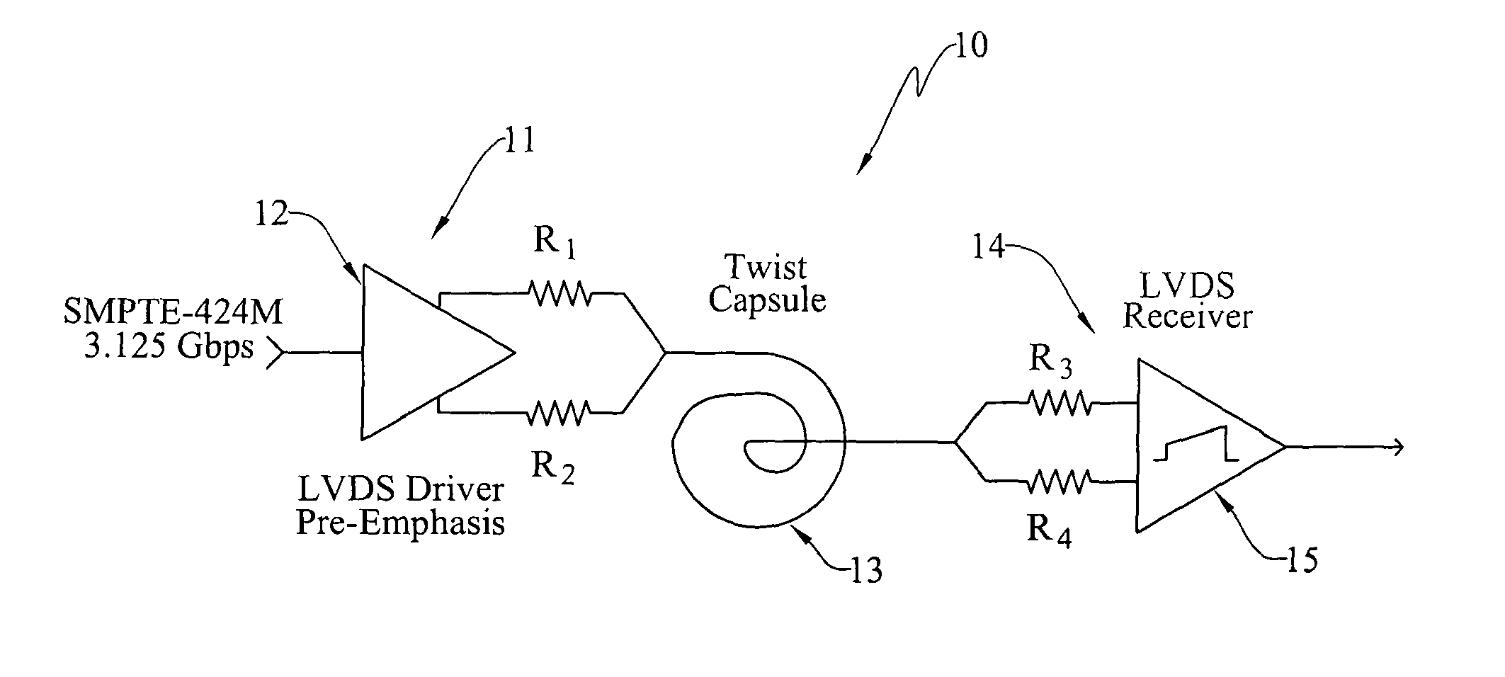
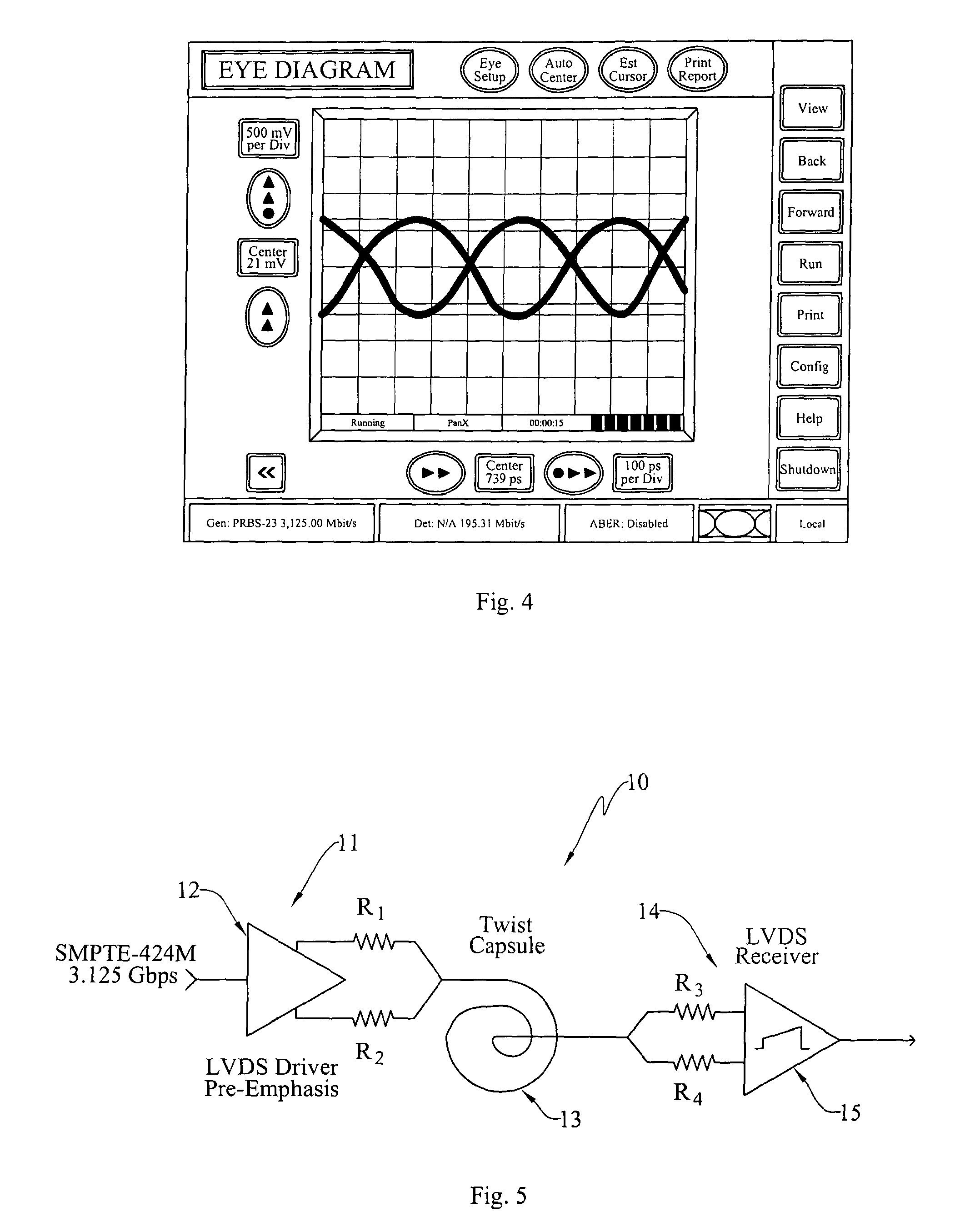
[0030]At the outset, it should be clearly understood that like reference numerals are intended to identify the same structural elements, portions or surfaces consistently throughout the several drawing figures, as such elements, portions or surfaces may be further described or explained by the entire written specification, of which this detailed description is an integral part. Unless otherwise indicated, the drawings are intended to be read (e.g., cross-hatching, arrangement of parts, proportion, degree, etc.) together with the specification, and are to be considered a portion of the entire written description of this invention. As used in the following description, the terms “horizontal”, “vertical”, “left”, “right”, “up” and “down”, as well as adjectival and adverbial derivatives thereof (e.g., “horizontally”, “rightwardly”, “upwardly”, etc.), simply refer to the orientation of the illustrated structure as the particular drawing figure faces the reader. Similarly, the terms “inwa...
PUM
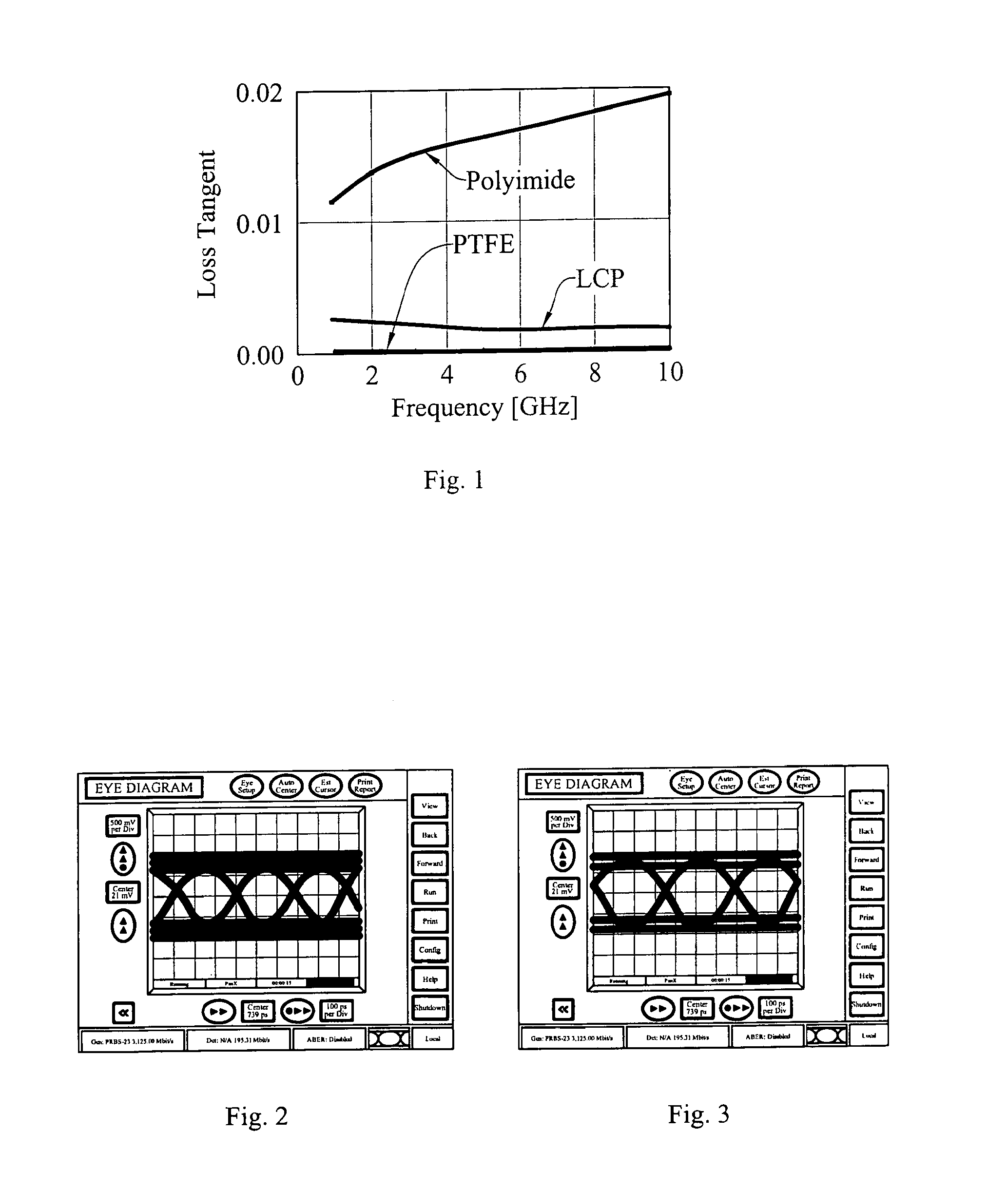
| Property | Measurement | Unit |
|---|---|---|
| dielectric loss | aaaaa | aaaaa |
| transition time | aaaaa | aaaaa |
| impedance | aaaaa | aaaaa |
Abstract
Description
Claims
Application Information