
Liquid crystal display device and backlight device thereof

a liquid crystal display device and backlight technology, applied in static indicating devices, lighting and heating apparatuses, instruments, etc., can solve the problems of one-board inverter method, lack of left and right balance of driving current delivered to the lamps, and method limitation in realizing a slim liquid crystal display device, etc. achieve the effect of avoiding an increase in thickness, reducing the thickness of the device, and ensuring the balance of driving signals

Inactive Publication Date: 2012-10-09
LG DISPLAY CO LTD
View PDF3 Cites 0 Cited by
  • Summary
  • Abstract
  • Description
  • Claims
  • Application Information

AI Technical Summary

Benefits of technology

[0013]An object of embodiments of the invention is to provide a liquid crystal display device that has slim profile by avoiding an increase in thickness due to an inverter.
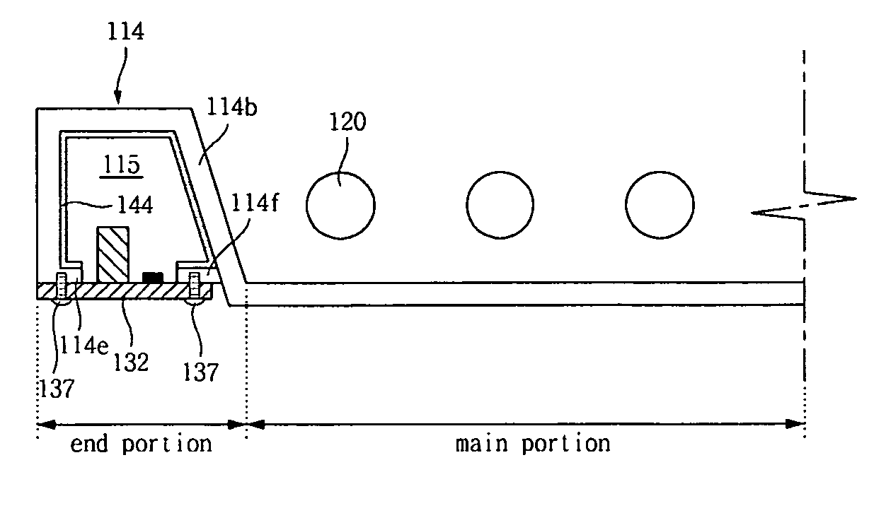
[0014]Another object of embodiments of the invention is to provide liquid crystal display devices that preserves the mountable space for a system module and provides balance in driving signals.
[0015]Another object of embodiments of the invention is to provide liquid crystal display devices that reduce electromagnetic interferences between an inverter and a system module.
[0016]Another object of embodiments of the invention is to provide liquid crystal display devices that have improved inverter efficiency.

Problems solved by technology

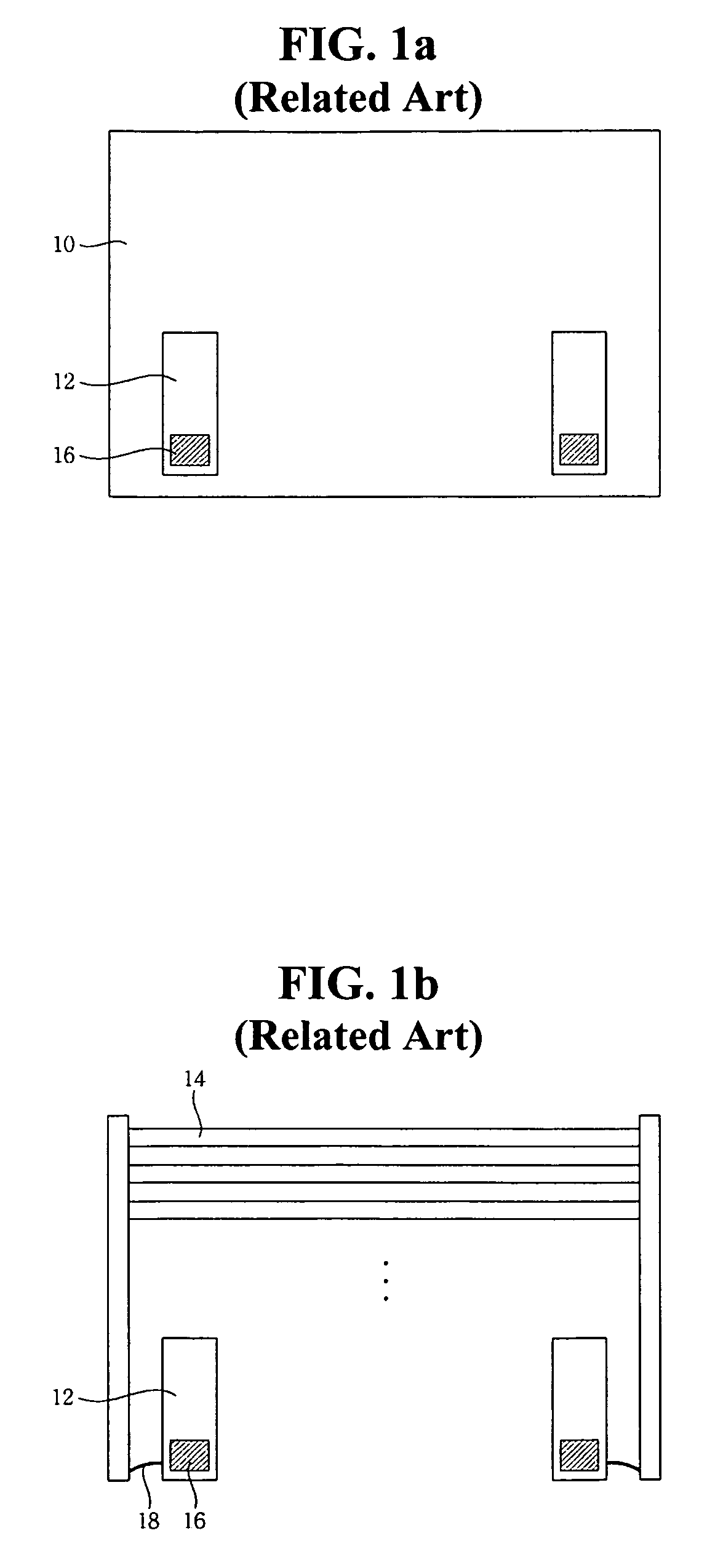
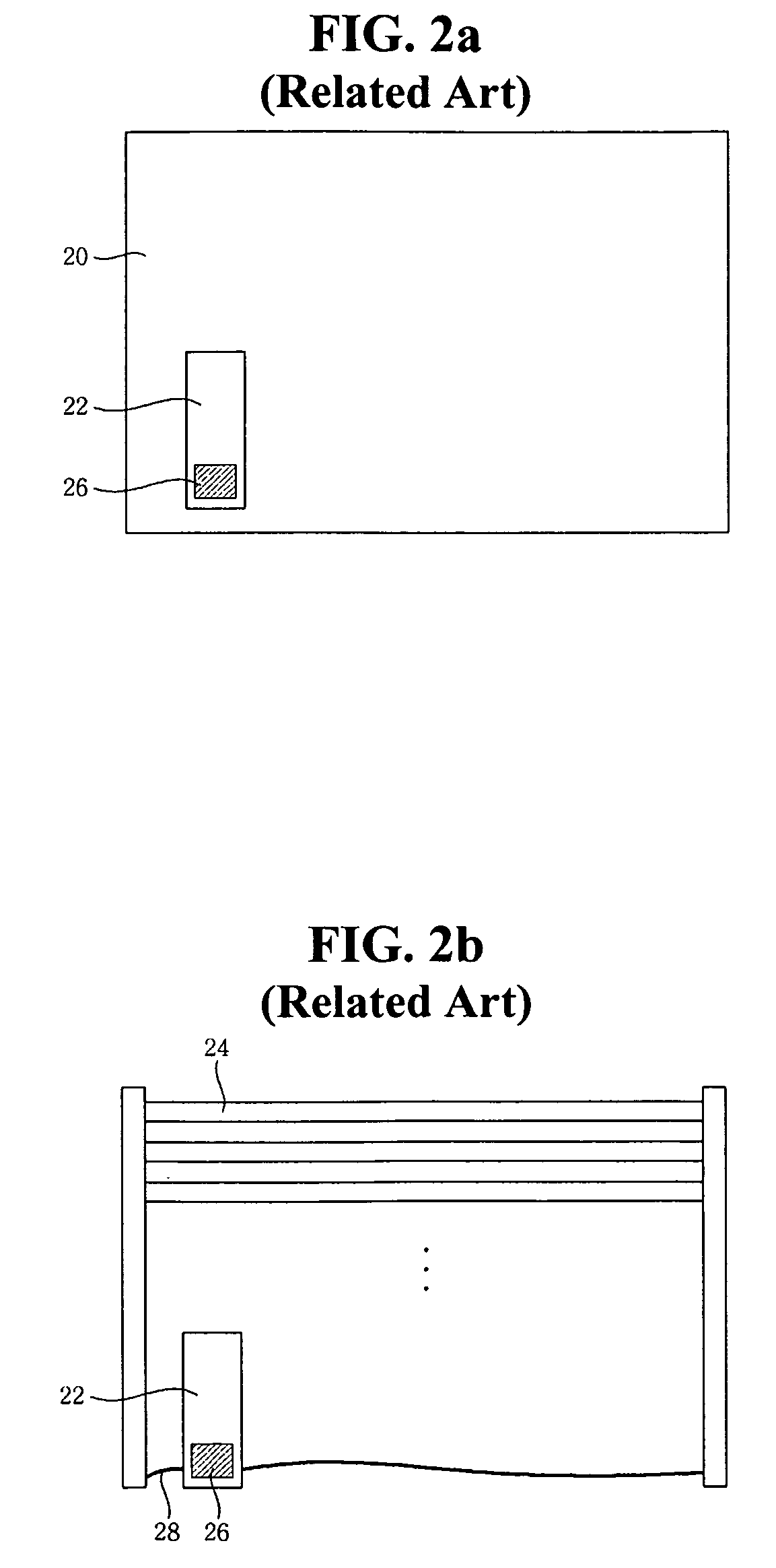
The one-board inverter method has a fatal disadvantage in that because the inverter 22 is arranged further toward either one side from both electrodes of the lamps 24, left and right balance of a driving current delivered to the lamps 24 is lacking.
Further, this method has another limitation in realizing a slim liquid crystal display device because the inverter 22 still projects from the back surface of the bottom cover 20 to the mounting height of the transformer 26.
Moreover, when the inverter according to the related art projects from the back surface of the bottom cover, the possibility that an electromagnetic interference may occur between the inverter and the system module increases.
Furthermore, because the inverter according to the related art is arranged adjacent to the electrodes of the lamps, heat generation of the inverter is increased by the lamp heat, thereby decreasing inverter efficiency.

Method used


Image

  • Liquid crystal display device and backlight device thereof
  • Liquid crystal display device and backlight device thereof
  • Liquid crystal display device and backlight device thereof

Examples


Embodiment Construction

[0040]Reference will now be made in detail to embodiments which are illustrated in the accompanying drawings. Wherever possible, similar reference numbers will be used to refer to the same or similar parts.

[0041]FIG. 3 is an exploded perspective view of a liquid crystal display device in accordance with an embodiment of the invention, and FIG. 4 is a view showing a lamp connection structure when an EEFL is implemented in accordance with an embodiment of the invention. Referring to FIGS. 3 and 4, a liquid crystal display device in accordance with an embodiment of the invention includes a top case 102, a liquid crystal display panel 106, a backlight unit, and an inverter 130.

[0042]The top case 102 covers the edges of the liquid crystal display panel 106. The liquid crystal display panel 106 includes an upper substrate 105 and a lower substrate 103. Liquid crystal materials (not shown) are formed between the upper substrate 103 and the lower substrate 105. The liquid crystal display pa...


PUM

PropertyMeasurementUnit
shapeaaaaaaaaaa
driving poweraaaaaaaaaa
weightaaaaaaaaaa

Abstract

A liquid crystal display device includes a liquid crystal display panel, a plurality of light sources for irradiating onto the liquid crystal display panel, at least two electrode boards at ends of each of the light sources for electrically connecting the light sources, an inverter board aligned parallel to the light sources for providing drive signals to the light sources through the electrode boards, and a first cover for accommodating the liquid crystal display panel, the light sources and the electrode boards on a first side thereof and for accommodating the inverter board on a second side thereof such that the inverter board is substantially on a same plane as a main portion of the cover.

Description

[0001]This application claims the benefit of Korea Patent Application No. 10-2008-0017996 filed on Feb. 27, 2008 in Korea and Korea Patent Application No. 10-2008-0039048 filed on Apr. 25, 2008 in Korea, which are respectively incorporated herein by reference for all purposes as if fully set forth herein.BACKGROUND OF THE INVENTION[0002]1. Field of the Invention[0003]The embodiments of the invention relate to a liquid crystal display device, and more particularly, to a slim-sized liquid crystal display device and a liquid crystal display device that maintains balance of a driving signal supplied to lamps in an accompanying light source.[0004]2. Discussion of the Related Art[0005]Generally, liquid crystal display devices are widely used due to advantageous characteristics of light weight, thin profile, and low power consumption. As a result, liquid crystal display devices are widely used in office automation equipment and audio / video equipment.[0006]A liquid crystal display device in...

Claims


Application Information

Patent Timeline
Patent Type & Authority Patents(United States)
IPC IPC(8): G02F1/1333G02F1/1335
CPCG02F1/133604H05B41/2822G09G3/3406F21V23/02G02F1/1335
Inventor GU, SEUNGMANJO, JAEWOO
Owner LG DISPLAY CO LTD
Learn More