Relating to scanning confocal microscopy

a technology of scanning confocal microscopy and confocal light, which is applied in the field of scanning confocal light microscopy, can solve the problems of slow and inefficient approach, and achieve the effect of smoother and more accurate beam movement and simplified computation of required steps

Active Publication Date: 2012-10-09
PEKINELMER SINGAPORE PTE LTD
View PDF11 Cites 51 Cited by
  • Summary
  • Abstract
  • Description
  • Claims
  • Application Information

AI Technical Summary

Benefits of technology

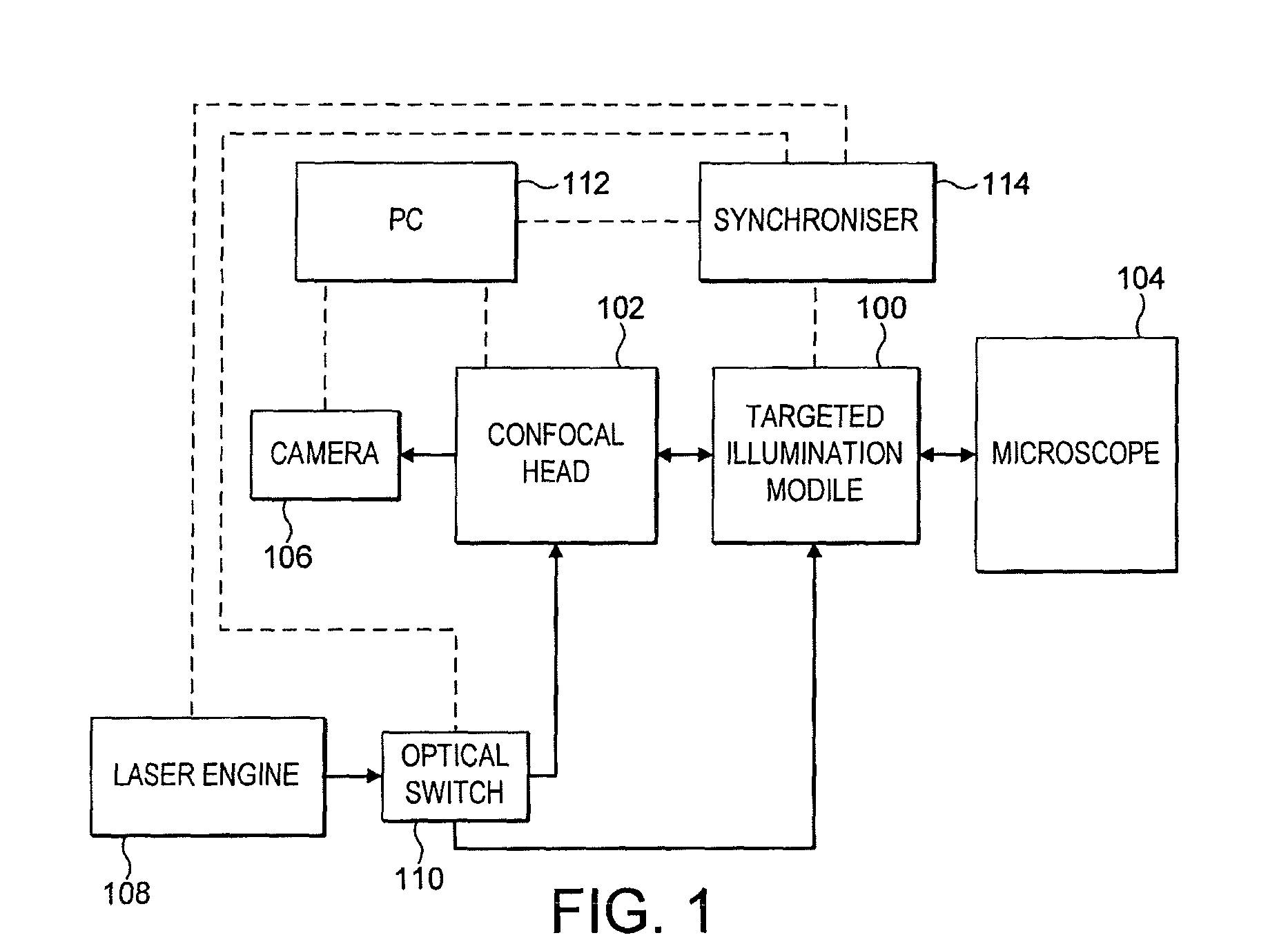
[0014]Arrangement of the microscope system such that the light beam from the assembly is selectively inputted into the same port as used by the confocal head is beneficial as it allows the coupling (switching) means to be located outside the microscope. The invention can therefore be implemented without requiring access to the interior of the microscope, or needing to accommodate additional components within the microscope.
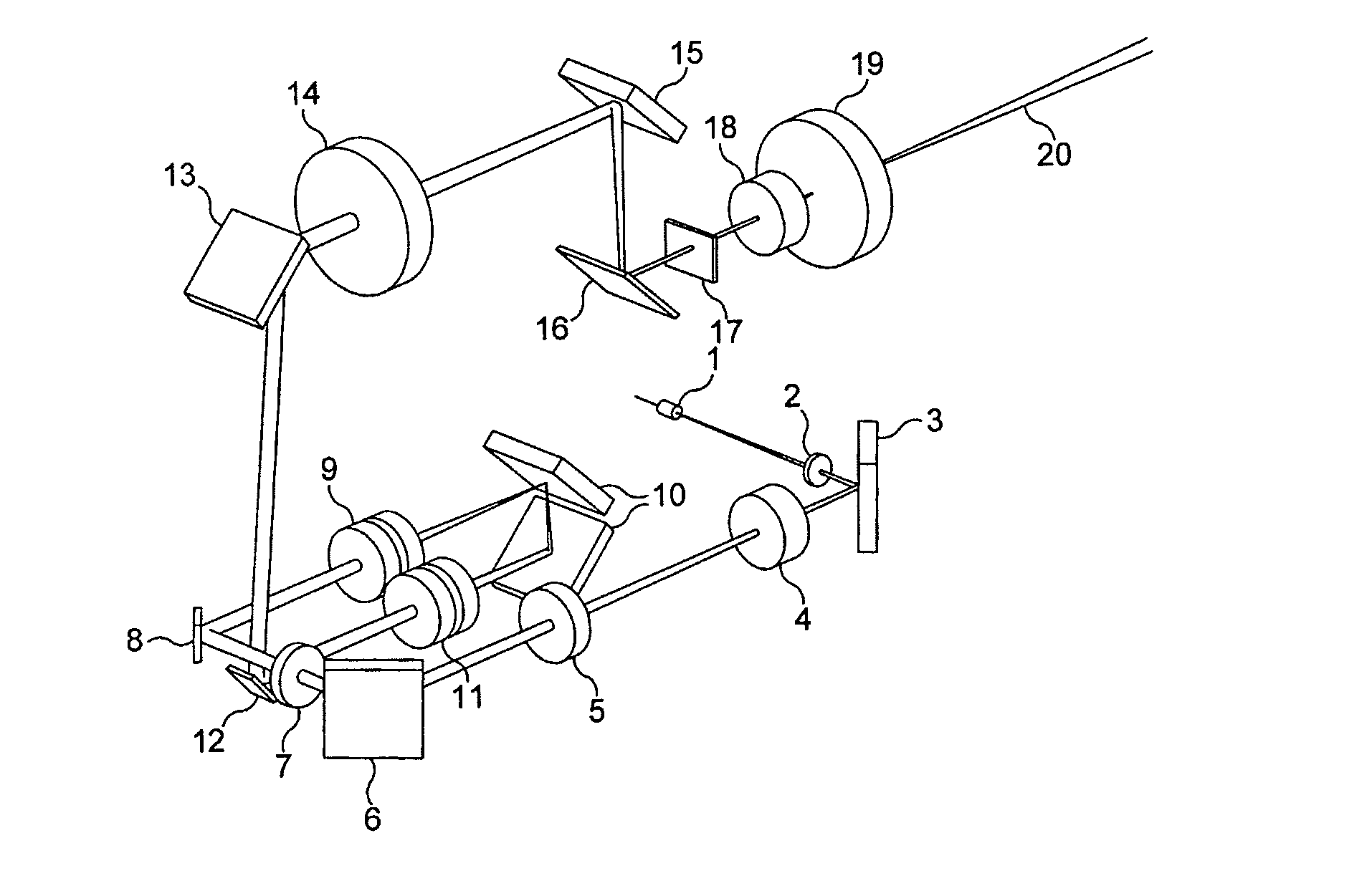
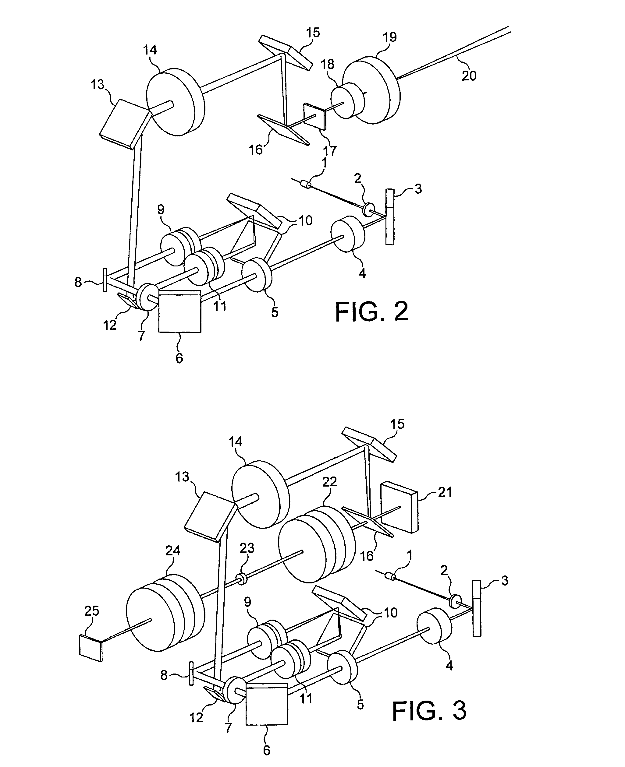
[0037]Advantageously, an optical relay may be provided in each light path through the optical switch, to reduce sensitivity to angular misalignment in the switch. The relay transfers the light input to the switch assembly to its output and focuses the input beam to a point between the input and the output. Preferably this point is close to the mirror of the switch (when in the second position).

Problems solved by technology

Despite the fact that such an approach is rather slow and inefficient, targeted illumination has been available on scanning spot systems for some years.
However, this is not the case for spinning disk systems where the parallel illumination of the optical arrangement gives no obvious opportunity to increase the light intensity dramatically over a specified region.

Method used


Image

  • Relating to scanning confocal microscopy
  • Relating to scanning confocal microscopy
  • Relating to scanning confocal microscopy

Examples


example

[0207]The following example is a typical pattern cycle and it demonstrates the usage of the internal command structure memory block.

[0208]

CommandGalvo nowSet Galvo X DAC PositionSet Galvo Y DAC PositionThe FPGA will load these values to the DAC and the Galvos will immediately move to the new positionLoad Pointer LaserLoad pointer laser, with the laser memory address value.This indicates the LASER memory location where the user has stored laser ON / OFF events. Multiple patterns can be stored in different memory locations.Load Pointer XLoad pointer galvo, with the laser memory address value.This indicates the GALVO memory location where the user has stored information for theGALVO vectors (for this specific pattern).DelayDelay time.StartFRAPNumber of vectors = ‘I’.The FPGA engine will executed ‘I’ GALVO vectors before it stops.StopFRAP

FPGA Implementation

Speed of Execution

[0209]The architecture of the FPGA allows the concurrent execution of the two main processes the GALVO and LASER eng...


PUM


Abstract

An assembly (100) and a method are provided for inputting a light beam into a light path extending from the confocal scanning head (102) to the microscope (104) of a scanning confocal microscope system to illuminate a selected region of a sample mounted in the microscope. The assembly comprises a light input for receiving a light beam from a light source; beam directing means (8, 12) for controlling the path of the light beam with reference to the shape of the selected region of the sample; and a beam coupler (16) for selective coupling the light beam into the light path from the confocal scanning head (102) to the microscope (104), with the beam direction being controlled by the beam directing means so as to illuminate the selected region. A scanning confocal microscope system including such an assembly is also described, together with a method of calibrating the system. In addition, an optical switch for selectively switching a light beam between two paths is disclosed.

Description

FIELD OF THE INVENTION[0001]The present invention relates to scanning confocal microscopy, and more particularly to selective illumination of one or more regions of a sample mounted in a scanning confocal microscope system.BACKGROUND TO THE INVENTION[0002]Confocal microscopes are used routinely for viewing internal details of semi-transparent microscopic bodies, especially in biological applications, often employing fluorescence illumination. The essential feature of such a microscope is the illumination of the sample by light focused through a pinhole, combined with observation of the returned light through the same pinhole, the result being that the detected light relates substantially to the specific image plane of the pinhole within the sample, rather than to planes above or below. This permits accurate depth resolution within the sample. Typically, a laser is used to provide a very tightly focused intense beam at the pinhole.[0003]As described above, such a system gives informa...

Claims


Application Information

Patent Timeline
Patent Type & Authority Patents(United States)
IPC IPC(8): G02B21/06
CPCG02B21/0028G02B21/0032G02B26/0816G02B21/0076G02B23/16
Inventor HOULT, ROBERT ALANBUSH, STEVE MORRISSEALY, GEORGE ROBERTKORONTZIS, DIONISIS
Owner PEKINELMER SINGAPORE PTE LTD
Why Eureka
Try Eureka