Universal post

a universal post and post technology, applied in the field of posts, can solve the problems of increasing material and labor costs, affecting the design of the intended use, and no known prior art device eliminates the dedicated use, etc., and achieves the effects of low cost, simple manufacturing, and simple design

Inactive Publication Date: 2012-10-16
WHITE JR WILLIAM J
View PDF25 Cites 8 Cited by
  • Summary
  • Abstract
  • Description
  • Claims
  • Application Information

AI Technical Summary

Benefits of technology

[0007]It is another object of this invention to provide a universal post that can be readily adaptable for use as a trash receptacle holder, a mail box support and a movable fence, one which is portable, in lieu of separate posts.
[0012]It is a further object of this invention to provide a universal post which may be manufactured from readily available materials by conventional manufacturing processes.
[0013]It is still a further object of this invention to provide a universal post that is simple in design, simple to manufacture, low in cost, safe and is easy and fun to use.
[0014]This invention results from the realization that there is a great need for a highly functional universal post suitable for multiple applications; the resulting invention provides such benefits.

Problems solved by technology

There are numerous prior art devices and methods for supporting objects, including signs, mail boxes and fence posts most of which involve a great deal of time and manual labor to implement or employ dedicated posts usable only for a specific application.
None of them are designed to be universally adaptable to various applications other than a single purpose; therefore separate posts and fences are necessary for each task thereby adding to material and labor costs.
Further, none of the known prior art devices eliminate the dedicated intended usage, for the particular post; therefore such posts are not universal.

Method used


Image

  • Universal post
  • Universal post
  • Universal post

Examples


Embodiment Construction

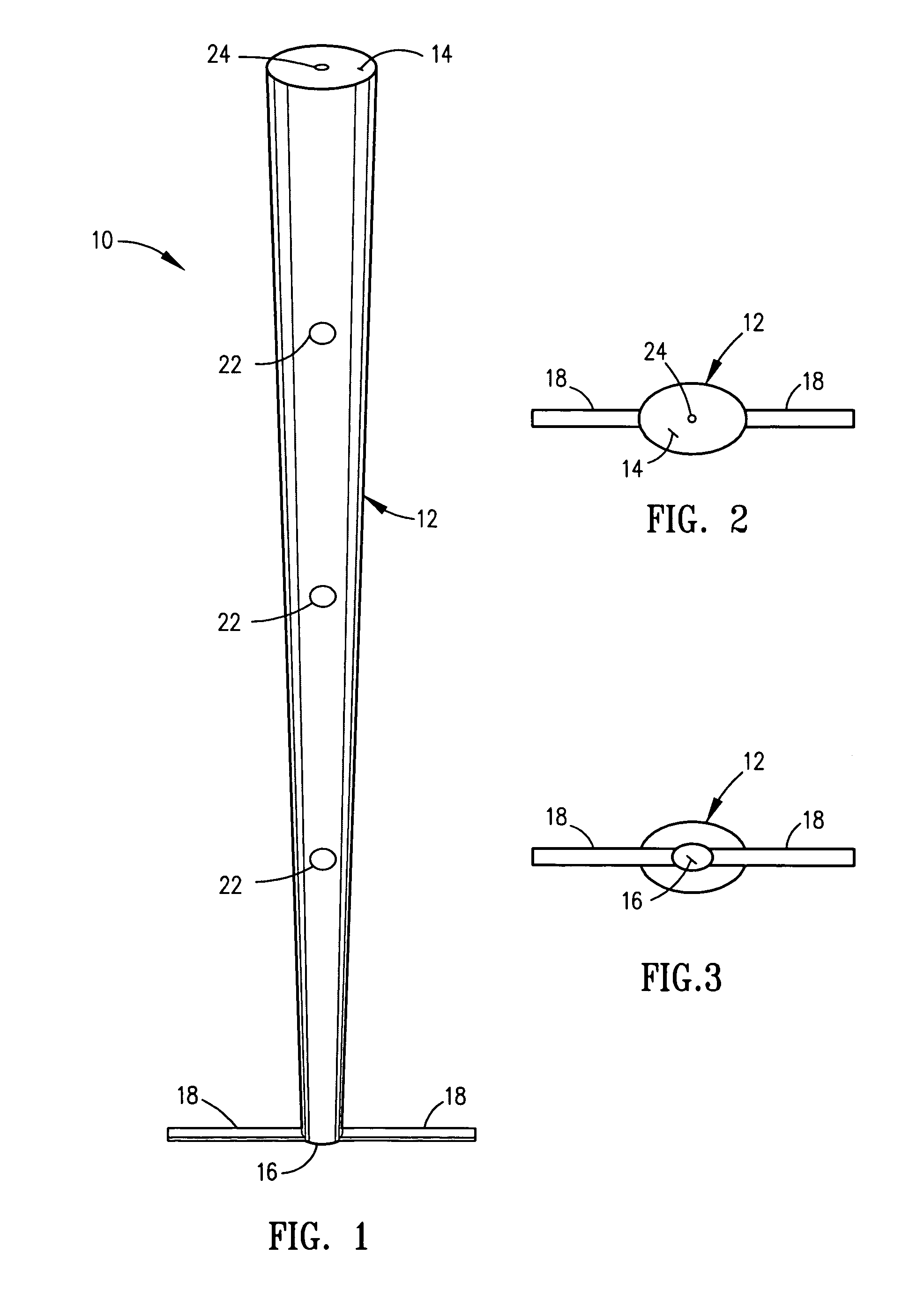
[0030]Looking more particularly to the drawings, there is shown in FIG. 1 an illustrative embodiment of a universal post, which is generally indicated at 10, according to an embodiment of the present invention.

[0031]FIG. 1 is a perspective view of an illustrative embodiment of a universal post of the instant invention.

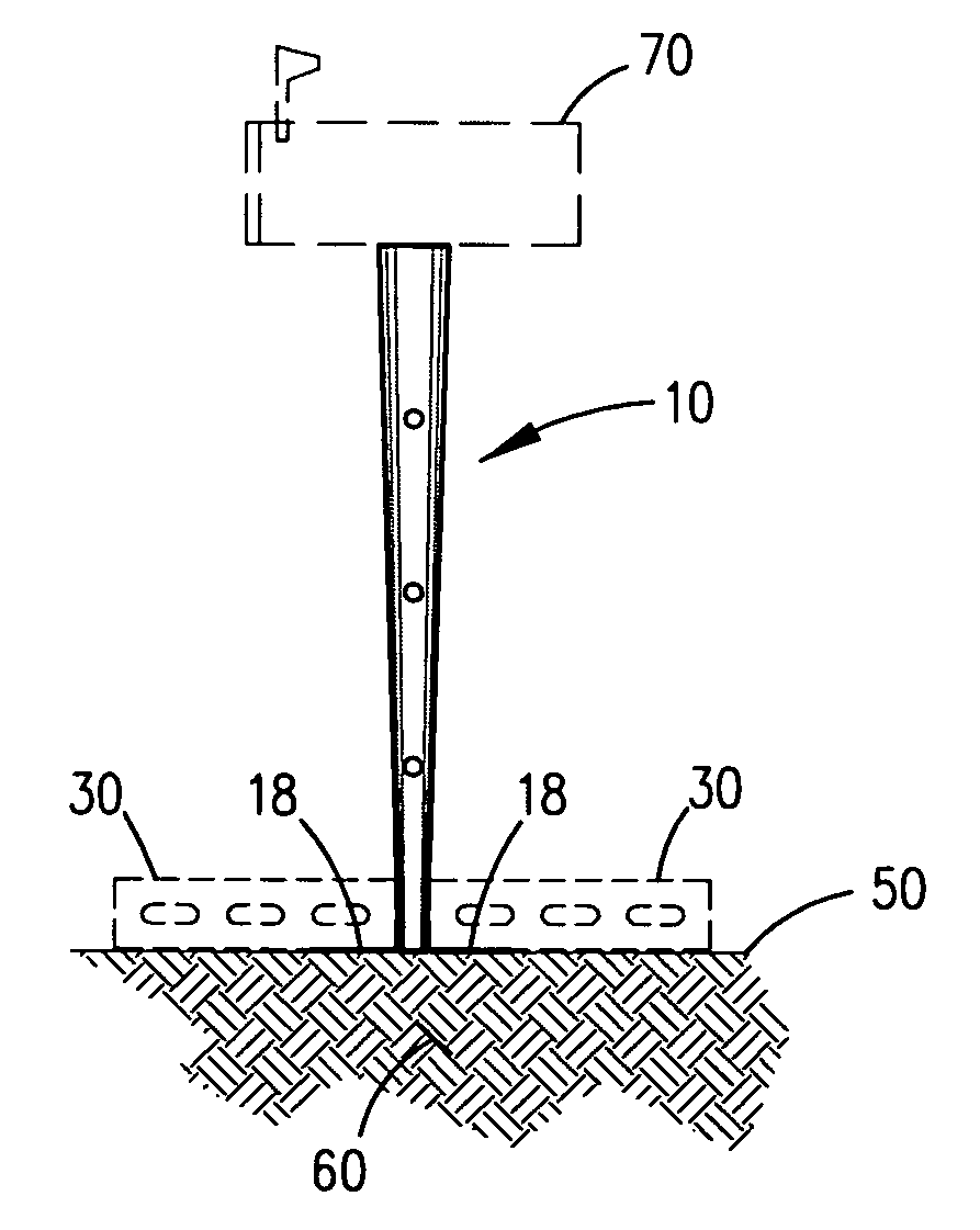
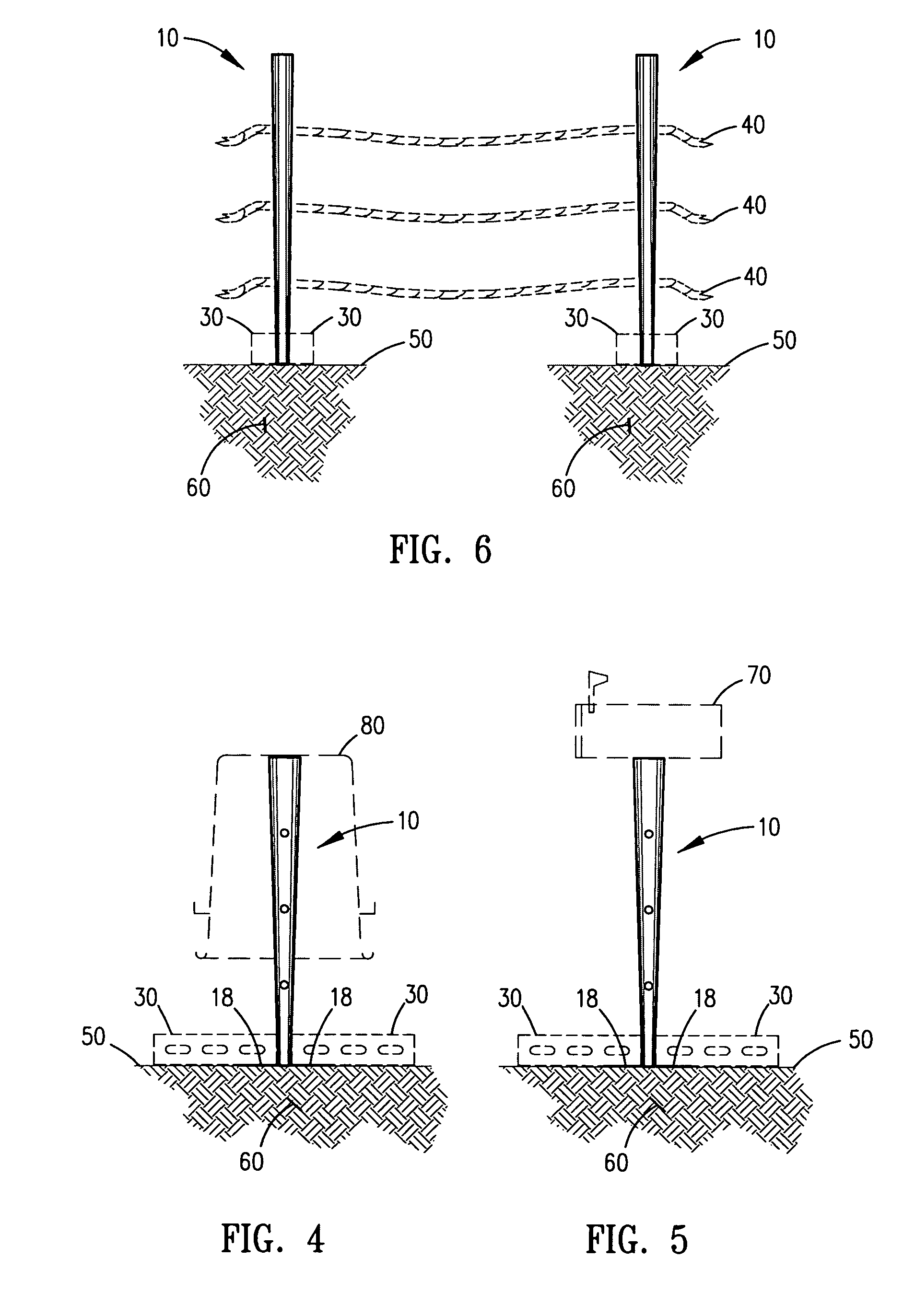
[0032]FIG. 1 shows a universal post 10 comprising an elongated member 12 having a proximal end 14 and a distal end 16. The elongated member 12 is tapered such that the proximal end 14 is larger in size than the distal end 16 of the elongated member 12 for receiving a trash receptacle 80 (shown in phantom in FIG. 4) thereon the proximal end 14 of the elongated member 12. Taper is critical for providing a suitable receiving surface thereon for the trash receptacle 80 (and a mail box 70 shown in phantom in FIG. 5). A stabilizer 18 is disposed orthogonal to and radially extending from the distal end 16 of the elongated member 12. The stabilizer 18 being substantially great...


PUM


Abstract

A universal post having a tapered elongated member with a proximal end and a distal end such that the proximal end is larger in size than the distal end of the elongated member for receiving one of a trash receptacle and a mail box thereon. A stabilizer is disposed orthogonal to and radially extending from the distal end of the elongated member. The stabilizer being substantially greater in length than width for placement on a ground surface so that a weighted member, received thereupon the stabilizer together with the stabilizer, supports the elongated member in a substantially vertical, stationary position with respect to the ground surface. The universal post capable of use on a flat paved surface and on a flat unpaved surface with the addition of a spike. The universal post further usable as a movable fence.

Description

FIELD OF THE INVENTION[0001]This invention relates generally to posts. More particularly, the present invention relates to a universal post for holding an empty trash receptacle; for supporting a mail box and for use with a rope as a movable portable fence.BACKGROUND OF THE INVENTION[0002]There are numerous prior art devices and methods for supporting objects, including signs, mail boxes and fence posts most of which involve a great deal of time and manual labor to implement or employ dedicated posts usable only for a specific application. None of them are designed to be universally adaptable to various applications other than a single purpose; therefore separate posts and fences are necessary for each task thereby adding to material and labor costs. Further, none of the known prior art devices eliminate the dedicated intended usage, for the particular post; therefore such posts are not universal.[0003]The inventor recognized a never before addressed problem and fulfilled a need whi...

Claims


Application Information

Patent Timeline
Patent Type & Authority Patents(United States)
IPC IPC(8): A45F3/44
CPCA47G29/1216B65F1/141E04H12/2215E04H17/08
Inventor WHITE, JR., WILLIAM J.
Owner WHITE JR WILLIAM J
Why Eureka
Try Eureka