
Flat heating element

a heating element and flat technology, applied in the field of flat heating elements, can solve the problems of fatigue and/or breakage, mechanical stress, and long-lasting use, and achieve the effects of long-lasting, corrosion-resistant, and economical

Inactive Publication Date: 2012-10-16
GENTHERM GMBH
View PDF111 Cites 43 Cited by
  • Summary
  • Abstract
  • Description
  • Claims
  • Application Information

AI Technical Summary

Benefits of technology

[0022]A goal of the present invention consists in producing a heating element which can be made to be sufficiently long-lasting, corrosion-resistant, and economical.

Problems solved by technology

Conductors which consist at least partially of copper can, however, only be mechanically stressed to a limited extent so that after longer-lasting use faults due to material fatigue and / or breaks can occur.
This is due primarily to the insufficient resistance to reverse bending stresses of the copper material.
In this case, an interruption of the supply of electricity occurs at the point of this break.
The heating element is then, at least in the areas through which current no longer flows, no longer capable of functioning.
However, there are instances of application in which the heating elements described there are still not always sufficiently robust and reliable.
However, if the silver is not applied so as to be pore-tight, the copper can be attacked nonetheless.
Furthermore, the silver diffuses into the copper over time.
Due to this, a boundary layer of Ag—Cu alloy forms which is very brittle.
Breaks of the boundary layer form initial cracks which also endanger the conductor.
An important disadvantage of these known combinations of material consists in the relatively high costs and the only limited resistance to corrosion of the jacketed wires.
However, it is not sufficiently resistant to corrosion for many intended uses.
Such an arrangement is, however, not very resistant to breaking.

Method used


Image

  • Flat heating element
  • Flat heating element
  • Flat heating element

Examples


Embodiment Construction

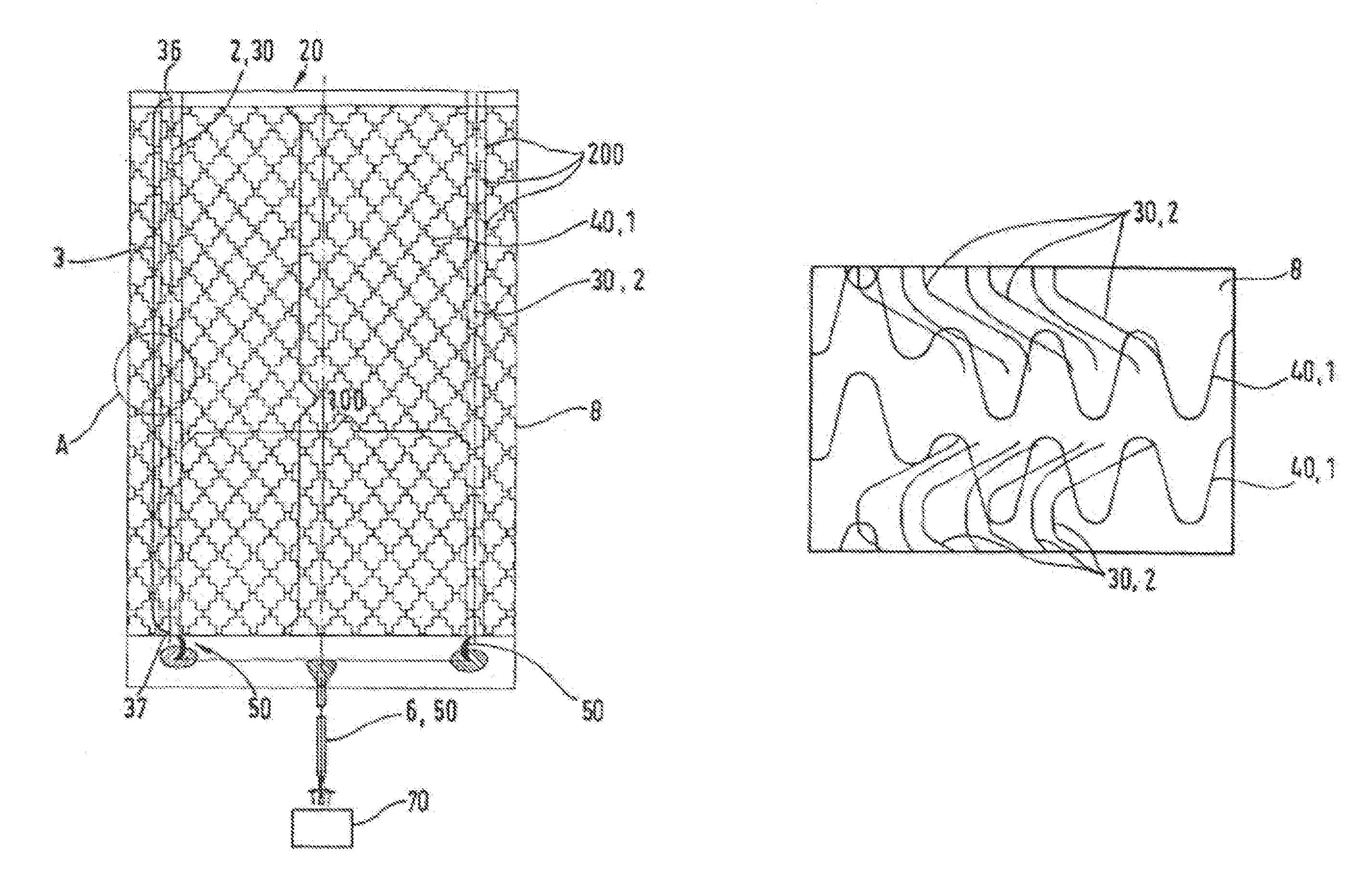
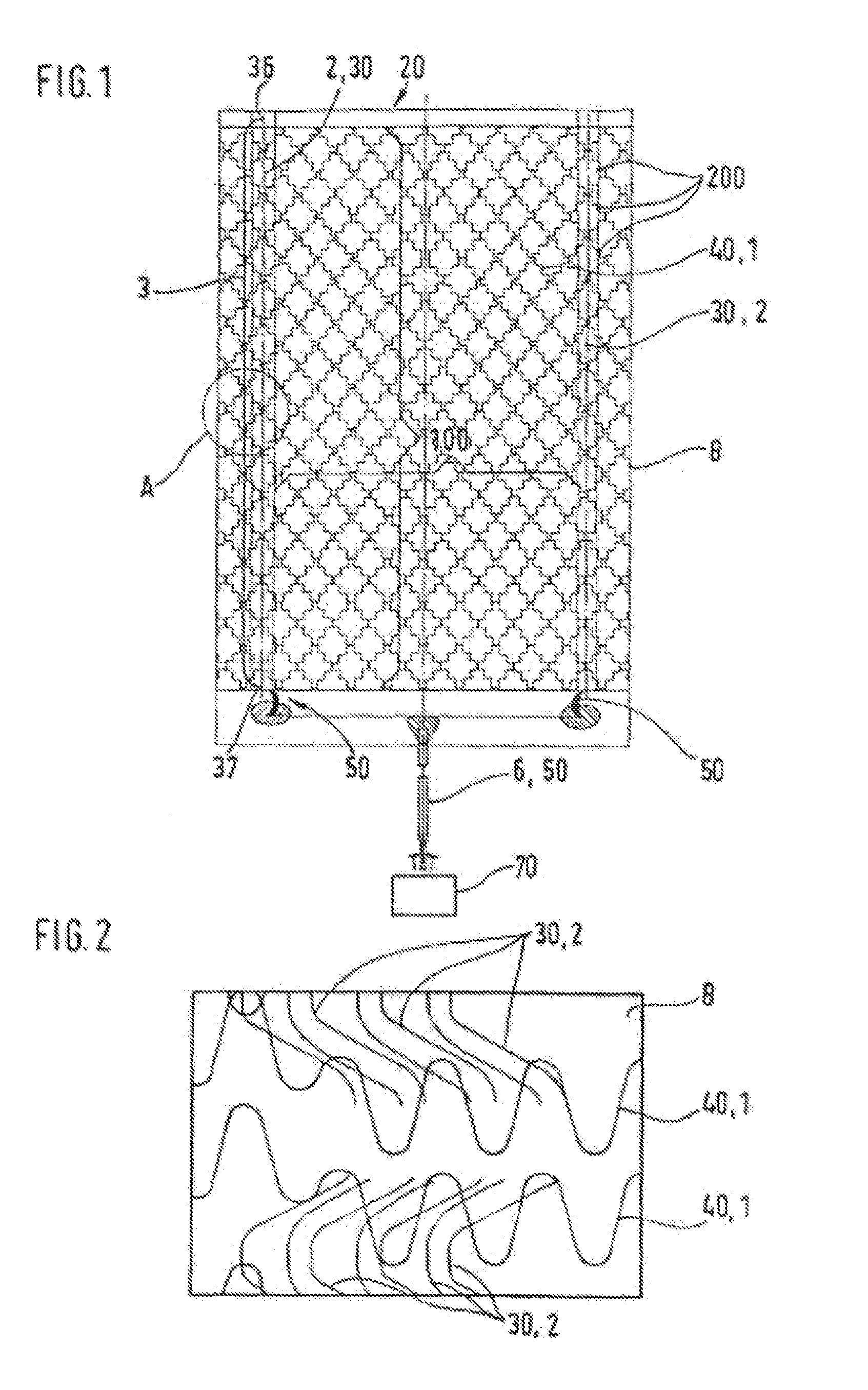
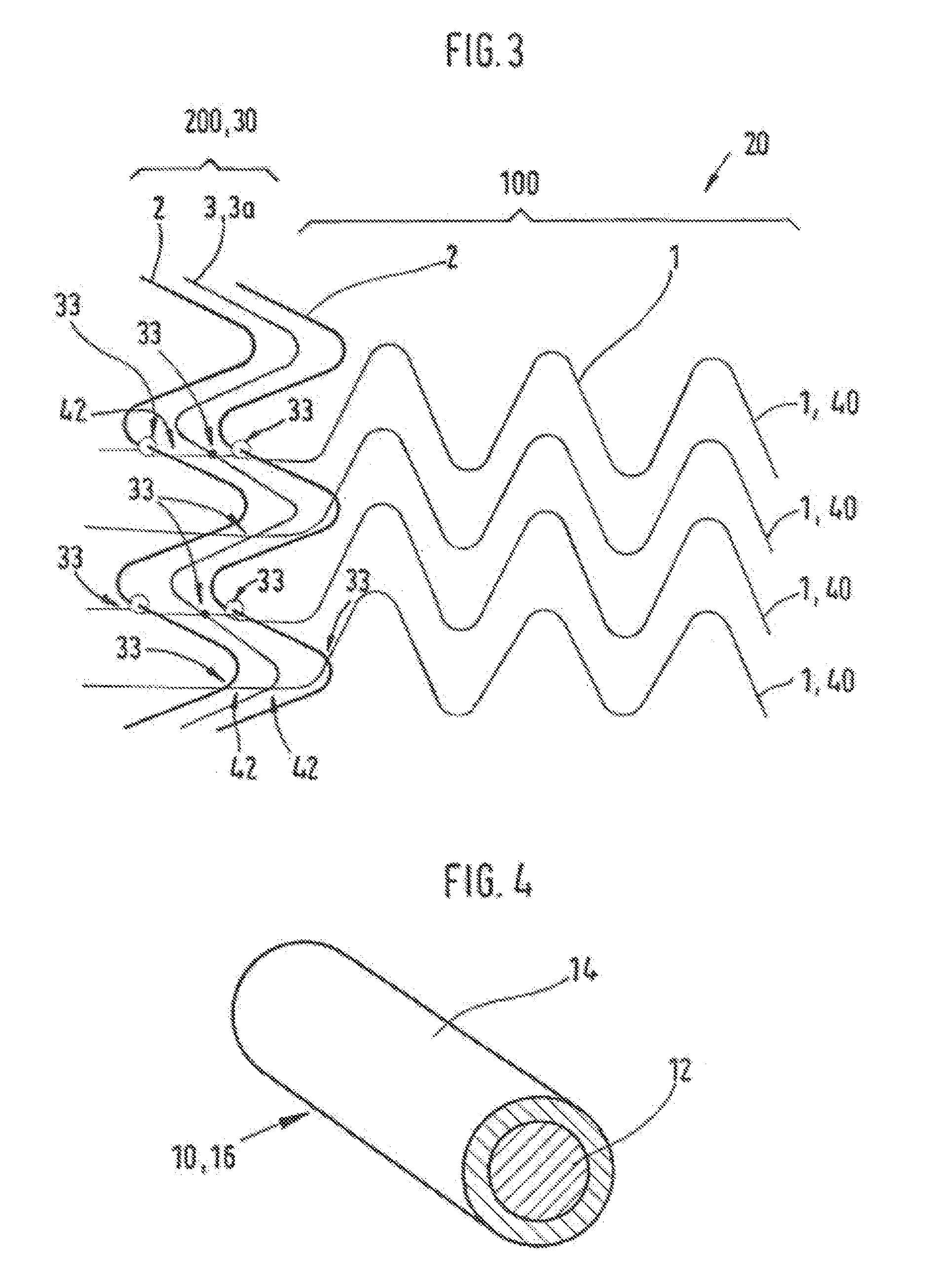
[0047]FIG. 1 shows an electrical element 20 with a flat carrier 8, with a pair of electrodes 30 which are disposed thereon spaced from one another and approximately parallel to one another and at contact areas 200 are connected, via a plurality of heating elements 40, to one another. The heat conductors 40 are disposed approximately parallel to one another on the carrier 8 and are electrically connected in parallel. The electrodes 30 for their part are connected, via electrical connecting lines 50, to a current source 70. The heat conductors 40 are formed from conductor strands 1 for heating of the heating element, preferably of carbonized plastic threads. The electrodes 30 are formed of conductor strands 2 for supplying electrical energy into the heating element 20, preferably of copper litz wires.

[0048]During operation, current flows from the current source, via a connecting line 6 and the one electrode 30, into the plurality of heat conductors 40. Their heating heats the heating ...


PUM


Abstract

The invention relates to a heating element (20), in particular for heating user contact surfaces of a passenger compartment of a vehicle, comprising a) at least one heating zone in which at least one first electrical conductor strand is disposed for heating a passenger of the automotive vehicle; b) at least one additional second conductor strand for supplying electrical energy into the at least one first conductor strand for heating the heating zone; c) a contact area in which the at least one additional second conductor strand is connected, in an electrically conductive manner, to the at least one first conductor strand for heating the heating zone; and wherein at least one of the first or second conductor strands includes at least one filament-like inner strand core comprising a polyamide, a carbon fiber, a polypropylene, or a polyester and at least one jacket layer that includes silver, copper, gold, nickel, or an alloy thereof.

Description

[0001]The present invention relates to a flat heating element, in particular for heating user-contacted surfaces of a passenger compartment of a vehicle, with at least one heating zone in which at least one electrical conductor strand is disposed for heating, with at least one additional conductor strand for supplying electrical energy into the at least one conductor strand for heating the heating zone, and with one contact area in which the conductor strand for supplying electrical energy is connected, in an electrically conductive manner, to the at least one conductor strand for heating the heating zone.THE STATE OF THE ART[0002]Known are flat heating elements with two or more contact conductors which are connected, in an electrically conductive manner, to one another by several heat conductors. These heat conductors and / or contact conductors can, for example, consist of copper or of another suitable conductor material with sufficient electrical conductivity and can in given cases...

Claims


Application Information

Patent Timeline
Patent Type & Authority Patents(United States)
IPC IPC(8): H05B3/03H05B3/18H05B3/36B60N2/56H05B3/34H05B3/56H05B3/84
CPCH05B3/342H05B3/56H05B3/84H05B2203/002H05B2203/003H05B2203/004H05B2203/005H05B2203/011H05B2203/017H05B2203/033
Inventor WEISS, MICHAELKOHLER, SIMONETREMMEL, PETER
Owner GENTHERM GMBH
Learn More