

Apparatus and method for rapid and accurate quantification of an unknown, complex mix
a technology of complex mix and apparatus, applied in the field of ultrahigh-sensitivity absorption spectroscopy, can solve the problems of inability to accurately identify the presence of minute quantities of compounds in gas or liquid at atmospheric pressure, introducing and being susceptible to measurement errors, so as to achieve less accurate and introduce complexity to the sample delivery mechanism
- Summary
- Abstract
- Description
- Claims
- Application Information
AI Technical Summary
Problems solved by technology
Method used
Image

Examples
example 1
Static Gas Measurement
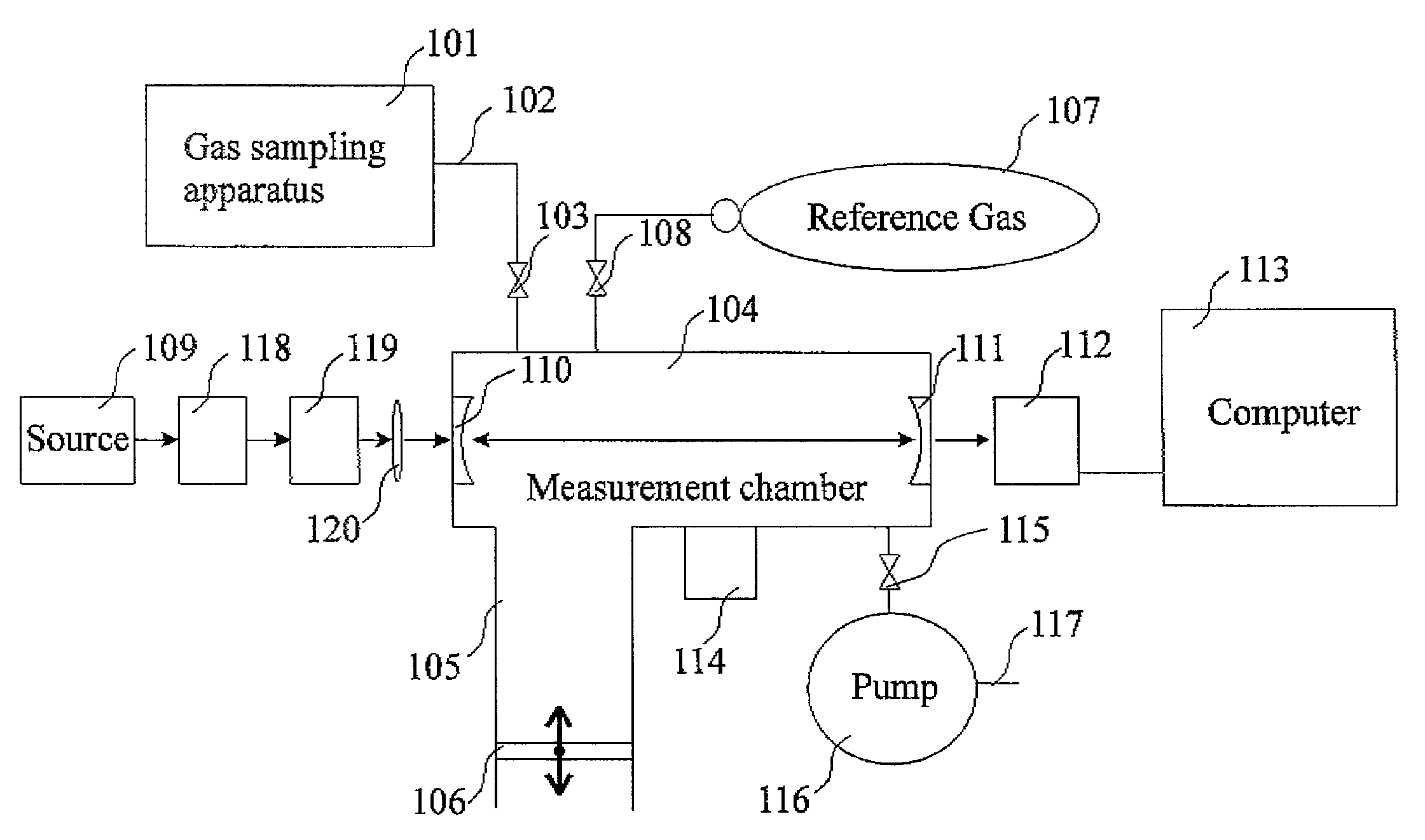
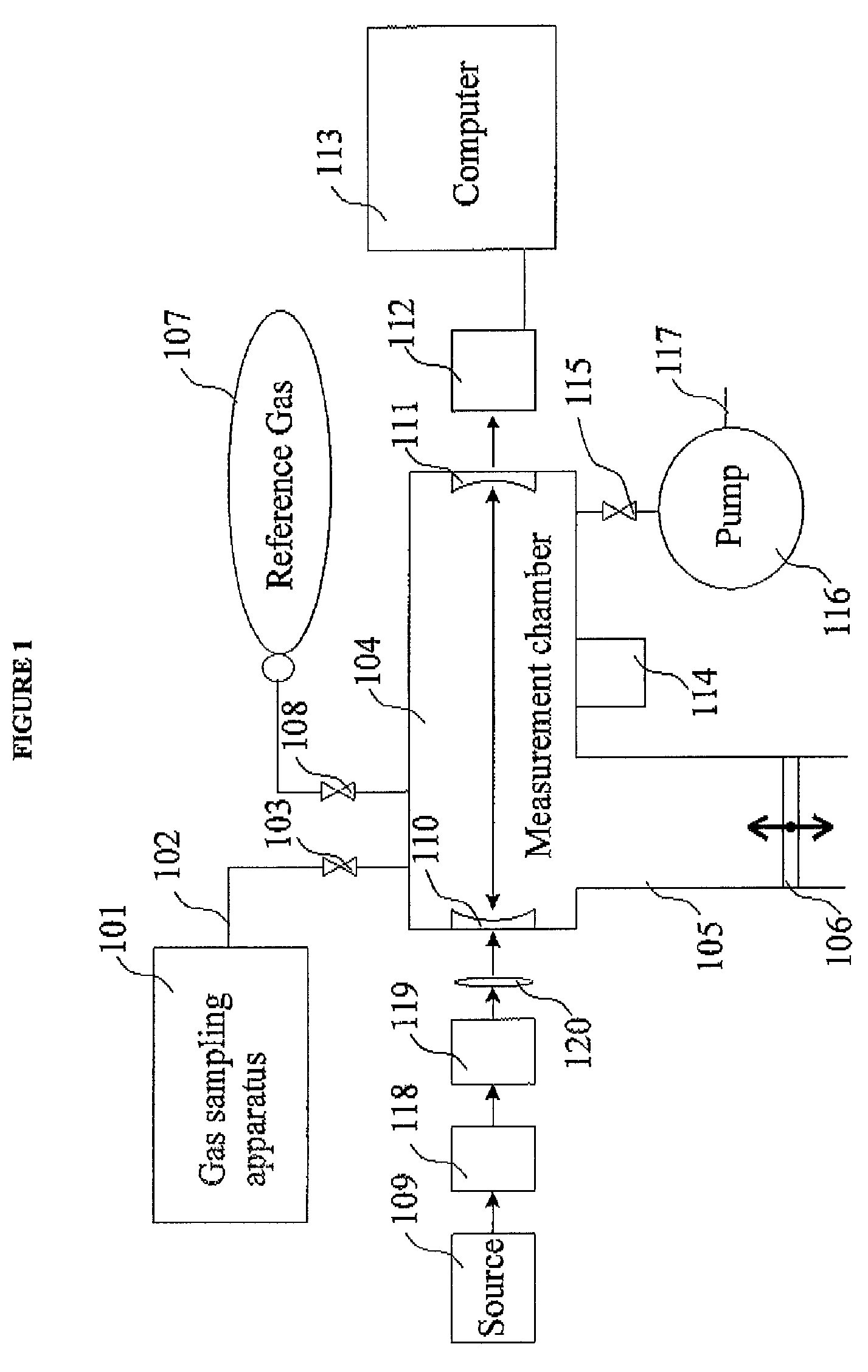
[0096]When using the preferred embodiment of the apparatus shown in FIG. 1, valves 103 and 108 are closed and valve 115 is opened. Measurement chamber 104 is then evacuated using pump 116. In the preferred embodiment, once an appropriately low measurement chamber pressure has been reached, valve 108 is closed and a series of ringdown measurements is then performed in the manner described in Section II. From these measurements, the ringdown time constant τ0(ν) is obtained for a series of source frequencies in a sequential manner. From the measured reference gas decay time constants and the complex gas mixture decay time constants, the optical densities k(ν) can be calculated for a series or source frequencies using EQ 4. Note that for this embodiment) kbg(ν)=0 in EQ 2 and EQ 3.
[0097]In an alternate embodiment of the reference measurement method, the reference measurement is performed by inserting a gas from reference gas cylinder 107 into measurement chamber 104...
example 2
Flowing Gas Measurement
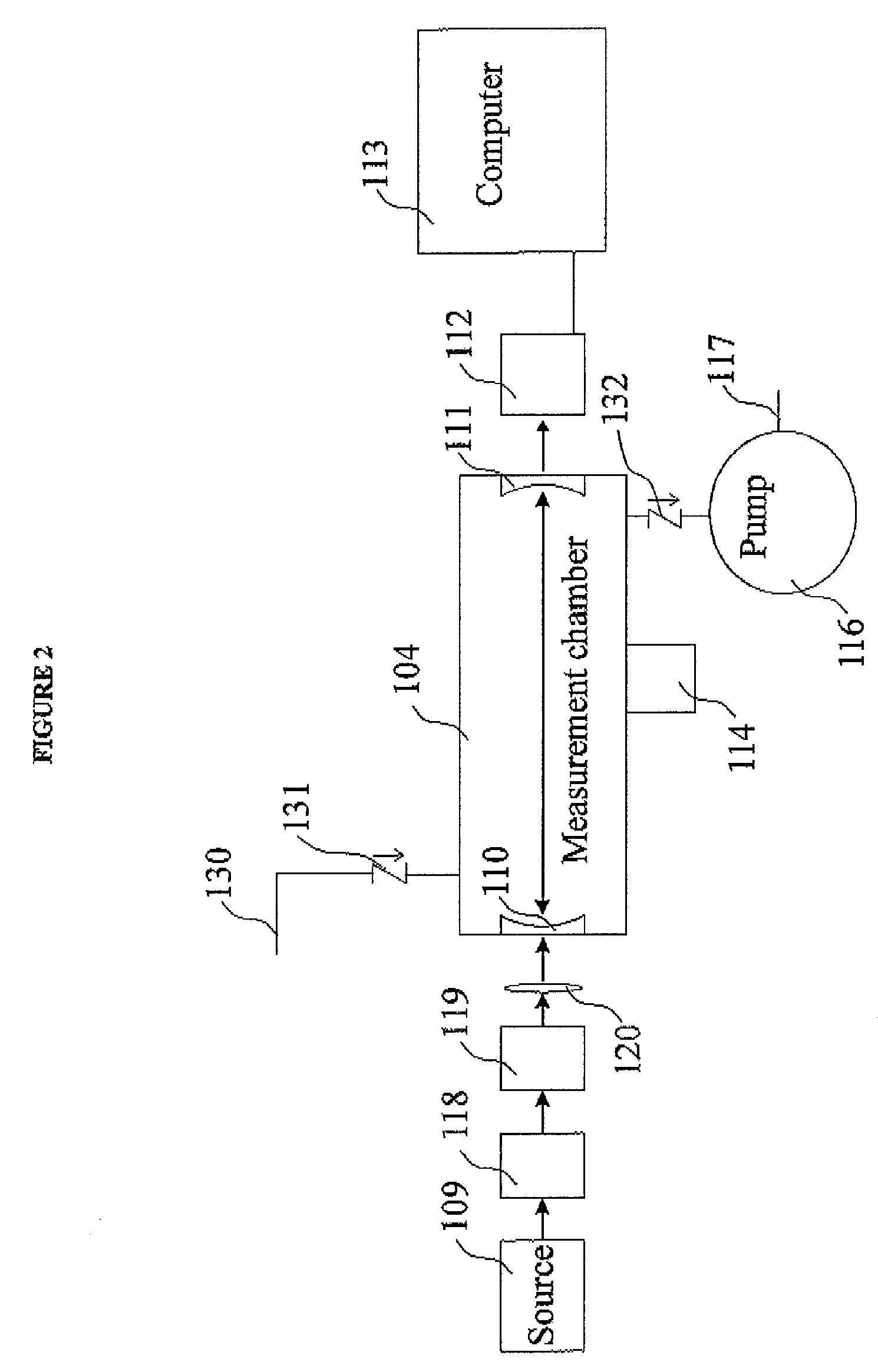
[0102]When using the gas flow measurement embodiment shown in FIG. 2, a reference measurement is a measurement of the gas flow taken at a time when the composition of said flow is known. With a gas of known composition flowing through the measurement chamber, a series of ringdown measurements is performed in the manner described in Section II. From these measurements, the ringdown time constant τ0(ν) is obtained for a series of source frequencies in a sequential manner. From the measured reference gas decay time constants and the complex gas mixture decay time constants, the optical densities k(ν) can be calculated for a series of source frequencies using EQ 4. Note that for this embodiment, kbg(ν) in EQ 2 and EQ 3 represents the combined optical densities from all the analytes in the known flowing reference gas.
example 3
Liquid Measurement
[0103]When using the liquid measurement embodiment shown in FIG. 3, a reference measurement is taken when there is no liquid inside chambers 141 and 142. The liquid is removed from said chambers by draining container 143 using outlet 144. A series of ringdown measurements is then performed in the manner described in Section II. From these measurements, the ringdown time constant τ0(ν) is obtained for a series of source frequencies in a sequential manner. From the measured reference decay time constants and the complex gas mixture decay time constants, the optical densities k(ν) can be calculated for a series or source frequencies using EQ 4. Note that for this embodiment kbg(ν)=0 in EQ 2 and EQ 3.
[0104]In an alternate embodiment of the reference measurement for liquids, the reference measurement is obtained by measuring the absorption by a liquid of known composition, for example pure water, in chambers 141 and 142. This is achieved by completely draining the compl...
PUM
| Property | Measurement | Unit |
|---|---|---|
| pressure | aaaaa | aaaaa |
| optical densities k(ν) | aaaaa | aaaaa |
| optical densities | aaaaa | aaaaa |
Abstract
Description
Claims
Application Information