
Video mode hidden autofocus

Active Publication Date: 2012-10-16
DIGITALPTICS MEMS
View PDF10 Cites 24 Cited by
  • Summary
  • Abstract
  • Description
  • Claims
  • Application Information

AI Technical Summary

Benefits of technology

[0011]One camera can be used to provide imaging and the other camera can be used to facilitate the autofocus process. Alternatively, both cameras can cooperate to facilitate the autofocus process, such as by use of triangulation or by the stereo effect. One of the cameras can provide video that does not include frames that are being tested for best focus. In this manner, the display of unfocused frames can be mitigated, while maintaining the display of the video stream.
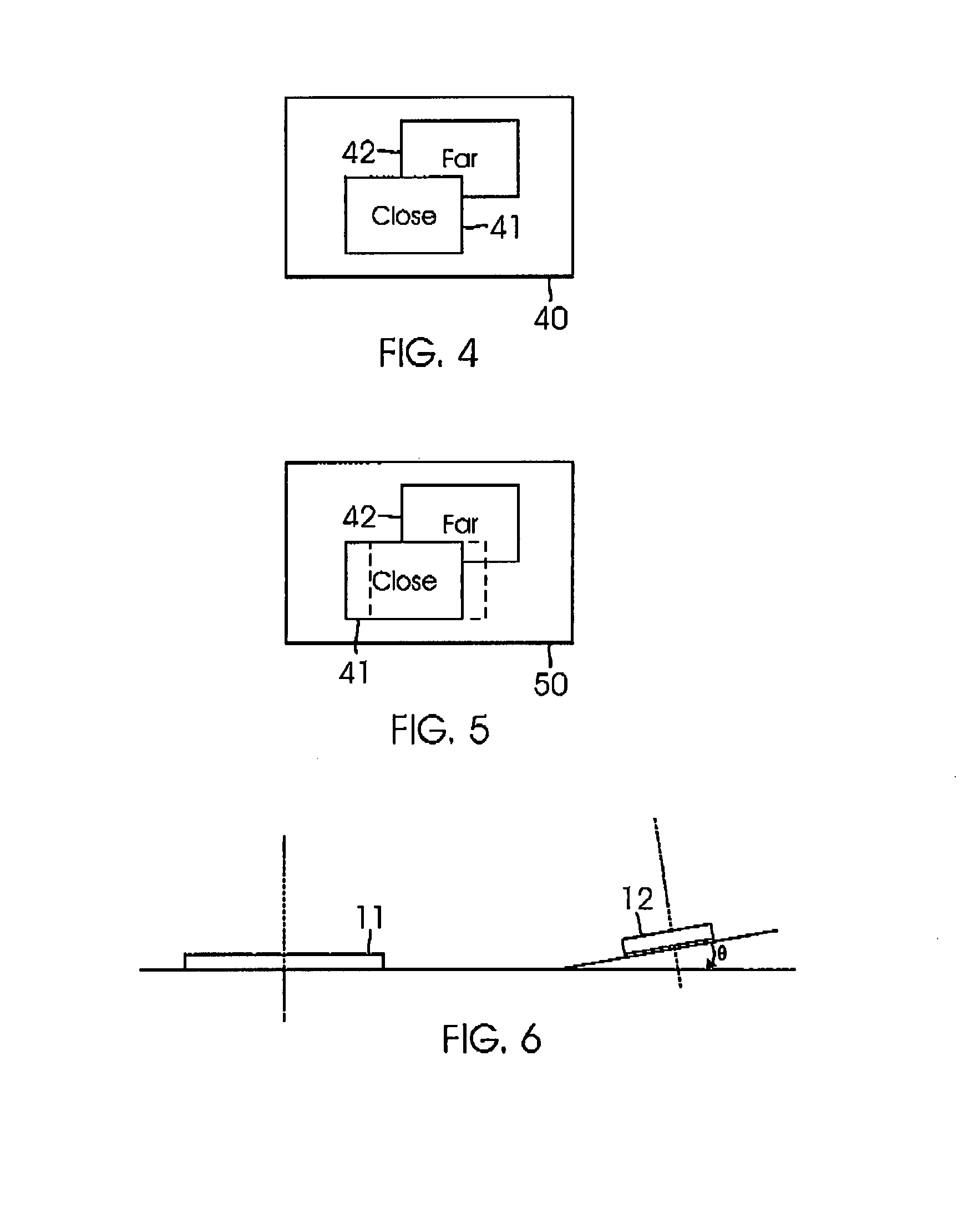
[0013]An embodiment comprises using two cameras to provide a stereo effect to determine a distance to a subject. The relative positions of objects in images from the two cameras can be indicative of their distance from the camera.
[0014]Benefits include improved enjoyment and ease of use of the cameras of personal electronic devices such as cellular telephones. More particularly, the annoyance and distraction caused by viewing out of focus frames during the autofocus process is mitigated.

Problems solved by technology

Although such autofocus mechanisms have proven generally suitable for their intended purpose, they do possess inherent deficiencies that tend to detract from their overall desirability.
Displaying such a series of images having constantly changing focus is undesirable.
More particularly, displaying a scene while the focus is changing can be annoying and distracting.
The distraction may even cause a user to miss the desired timing of a shot, particularly for a moving subject.

Method used


Image

  • Video mode hidden autofocus
  • Video mode hidden autofocus
  • Video mode hidden autofocus

Examples


Embodiment Construction

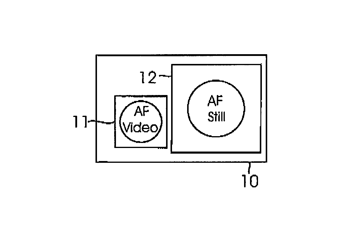
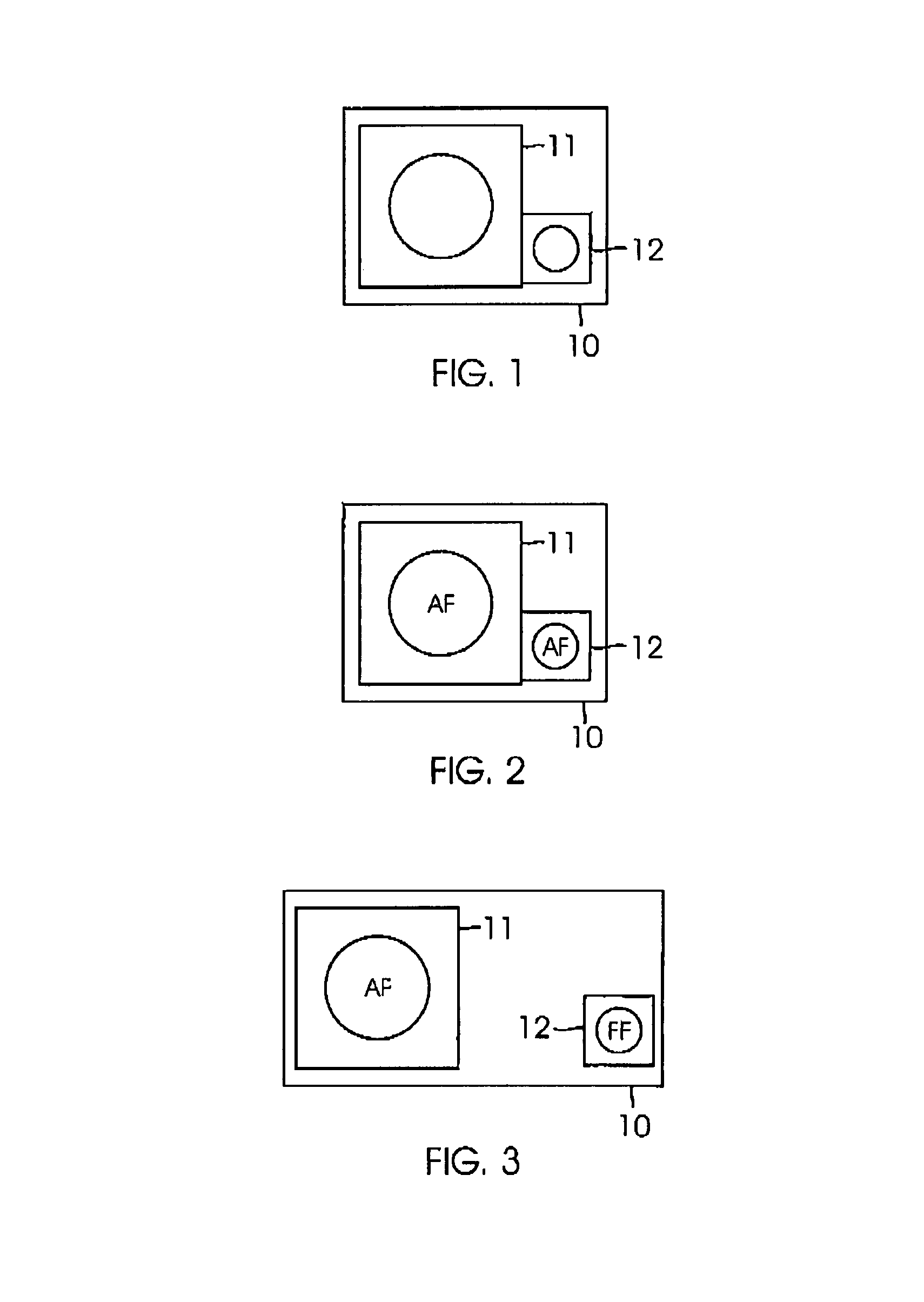
[0028]A method and system for hiding objectionable frames during autofocusing are disclosed. Such objectionable frames include frames that are unfocused and / or changing in focus. A personal electronic device such as a cameral telephone can have two cameras that have overlapping fields of view. One camera can provide imaging. The other camera can facilitate autofocusing in a manner wherein images produced thereby are not viewed by a user. Because the autofocus frames are hidden, the user is not distracted or annoying thereby.

[0029]Contemporary autofocus cameras display frames while changing the focusing lens position during the autofocus process. One or more embodiments provide methods and systems that use multiple cameras to facilitate performance of the autofocus process in the background.

[0030]Referring now to FIG. 1, multiple cameras such as first camera 11 and second camera 12 can be positioned on the same side of a personnel electronic device 10 so that they point substantially...


PUM


Abstract

A method and system for hiding objectionable frames during autofocusing are disclosed. A personal electronic device such as a cameral telephone can have two cameras that have overlapping fields of view. One camera can provide imaging. The other camera can facilitate autofocusing in a manner wherein images produced thereby are not viewed by a user. Because the autofocus frames are hidden, the user is not distracted or annoying thereby.

Description

TECHNICAL FIELD[0001]The present invention relates generally to video imaging. The present invention relates more particularly to a method and system for mitigating the display of unfocused frames during the autofocus process.BACKGROUND[0002]Autofocus mechanisms for cameras are well known. Such autofocus mechanisms typically move one or more lenses of a camera so as to achieve desired sharpness or focus of an image. Autofocus mechanisms can be either active or passive. Active autofocus mechanisms determine a distance to the subject and then move one or more lenses to a position that has been determined to provide proper focus for that distance. Passive autofocus mechanisms determine the sharpness of images as the focusing lens(es) are moved, so as to determine the particular position where the best focus is obtained.[0003]The distance to the subject can be determined by measuring the time that it takes for a signal, such as infrared light or ultra high frequency sound, to travel to ...

Claims


Application Information

Patent Timeline
IPC IPC(8): H04N13/02H04N13/239
CPCH04N5/2258H04N5/23212H04N13/0239H04N13/239H04N23/45H04N23/673
Inventor TSAI, RICHARDLIU, XIAOLEI
Owner DIGITALPTICS MEMS
Learn More