Image recording method, image recording apparatus, and image recording medium

a technology of image recording and recording medium, which is applied in the field of image recording method, image recording apparatus, and image recording medium, can solve the problems of long exposure time and inability to obtain smooth images, and achieve the effects of low cost, reduced exposure area of one elemental hologram, and advantageous production

Inactive Publication Date: 2012-10-16
SONY CORP
View PDF5 Cites 0 Cited by
  • Summary
  • Abstract
  • Description
  • Claims
  • Application Information

AI Technical Summary

Benefits of technology

[0010]FP holographic stereograms can be produced at low cost because an optical system can be composed of a combination of spherical lenses. In addition, since dot-shaped elemental holograms are recorded in the FP holographic stereograms, the exposure area of one elemental hologram can be decreased. As a result, the FP holographic stereograms can be produced advantageously at low shutter speeds with a low power laser. However, if the area of each elemental hologram is small, since the number of elemental holograms necessary for surface exposure increases, the exposure time becomes long. In addition, since boundaries of elemental holograms are visible, smooth images are not obtained.
[0011]In view of the foregoing, it would be desirable to provide an image recording method, an image recording apparatus, and an image record medium that provide vertical parallaxes along with high image quality and high speed of HPO holographic stereograms.
[0019]According to an embodiment of the present invention, there is provided an image recording apparatus which records a holographic stereogram. The image recording apparatus includes an optical deflecting device and an exposure control section. The optical deflecting device includes a spatial light modulation device, an anamorphic optical system having different aspect ratios, and an optical deflecting element having a plurality of refraction angles at which beam is refracted in its long side direction and being movable in parallel with a record medium, the optical deflecting device being disposed in proximity to a hologram record medium when it is exposed with a stripe-shaped elemental hologram, the optical deflecting device deflecting either object beam or reference beam in a long side direction thereof to expose the hologram record medium. The exposure control section multiply exposes the hologram record medium at least two times with different deflection angles of the optical deflecting device to cause the elemental hologram to have a plurality of parallaxes in a long side direction of the elemental hologram.
[0020]According to an embodiment of the present invention, there is provided an image record medium on which a holographic stereogram is recorded. The holographic stereogram is produced by disposing an optical deflecting device in proximity to a hologram record medium when it is exposed with a stripe-shaped elemental hologram, deflecting either object beam or reference beam in a long side direction thereof through the optical deflecting device to expose the hologram record medium, and multiply exposing the hologram record medium at least two times with different deflection angles of the optical deflecting device to cause the elemental hologram to have a plurality of parallaxes in a long side direction of the elemental hologram.
[0021]As is clear from the foregoing description, according to an embodiment of the present invention, a full parallax type holographic stereogram having independent vertical parallaxes and horizontal parallaxes can be produced with high quality using an optical system, a mechanical section, and a control section that record elemental holograms having horizontal parallaxes. Thus, a holographic stereogram that has higher image quality, higher speed, and less remarkableness of boundaries of elemental holograms than those of a dot-shaped full-parallax type holographic stereogram can be produced.

Problems solved by technology

However, if the area of each elemental hologram is small, since the number of elemental holograms necessary for surface exposure increases, the exposure time becomes long.
In addition, since boundaries of elemental holograms are visible, smooth images are not obtained.

Method used


Image

  • Image recording method, image recording apparatus, and image recording medium
  • Image recording method, image recording apparatus, and image recording medium
  • Image recording method, image recording apparatus, and image recording medium

Examples


Embodiment Construction

[0038]Next, with reference to the accompanying drawings, several specific embodiments of the present invention will be described in detail. It should be noted that the present invention is not limited to the following examples and that they may be modified without departing from the scope and spirit of the present invention.

[0039]The relationship between the elements of the Claims and the elements of the embodiments is as follows.

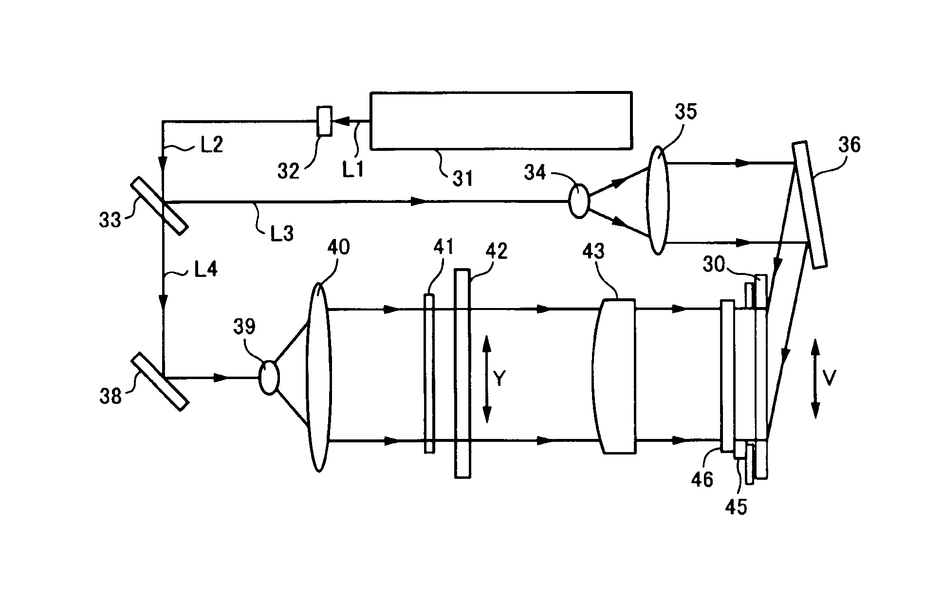
[0040]In a holographic stereogram, stripe-shaped elemental holograms are recorded on a hologram record medium 30. A prism sheet 46 is used as an optical deflecting device. One of object beam L4 and reference beam L3 is deflected in the long side direction through the prism sheet 46 such that a hologram record medium 30 is exposed with the object beam L4 and the reference beam L3. By multiply exposing the hologram record medium at least two times with the object beam L4 and the reference beam L3 at different deflection angles (refraction angles of the prism ...


PUM


Abstract

Recording an image of a holographic stereogram includes providing an optical deflecting device in proximity to a hologram recording medium that is exposed with a stripe-shaped elemental hologram. Either an object beam or a reference beam is deflected, in a long side direction thereof, through the optical deflecting device to expose the hologram recording medium. The hologram recording medium is multiply exposed, at least twice, with different deflection angles of the optical deflecting device to cause the stripe-shaped elemental hologram to have a plurality of parallaxes in a long side direction of the stripe-shaped elemental hologram.

Description

CROSS REFERENCES TO RELATED APPLICATIONS[0001]The present invention contains subject matter related to Japanese Patent Application JP 2007-288327 filed in the Japanese Patent Office on Nov. 6, 2007, the entire contents of which being incorporated herein by reference.BACKGROUND OF THE INVENTION[0002]1. Field of the Invention[0003]The present invention relates to an image recording method and apparatus that produce holographic stereograms having parallaxes both in the horizontal (left and right) directions and vertical (upper and lower) directions and to an image record medium on which the holographic stereograms are recorded.[0004]2. Description of the Related Art[0005]A hologram of a three-dimensional image can be produced using two-dimensional original images of an object taken from different view points. A holographic stereogram is produced, for example, by successively recording many original images of which an object is taken from different observation points as stripe-shaped or...

Claims


Application Information

Patent Timeline
Patent Type & Authority Patents(United States)
IPC IPC(8): G03H1/26G03H1/10G03H1/04
CPCG03H1/268G03H1/28G03H2001/0415G03H2001/2239G03H2223/18
Inventor SHIRAKURA, AKIRANAKAGAWA, YUJIKIHARA, NOBUHIRO
Owner SONY CORP
Why Eureka
Try Eureka