Roof mounted air hose and electrical cord holder

a technology of air hose and air holder, which is applied in the direction of door/window, religious equipment, antenna details, etc., and can solve problems such as inability to summariz

Active Publication Date: 2012-10-23
SCHINDLER TERRENCE R +1
View PDF15 Cites 14 Cited by
  • Summary
  • Abstract
  • Description
  • Claims
  • Application Information

AI Technical Summary

Problems solved by technology

Moreover, this Summary is not intended for use as an aid in determining the scope of the claimed subject matter.

Method used


Image

  • Roof mounted air hose and electrical cord holder
  • Roof mounted air hose and electrical cord holder
  • Roof mounted air hose and electrical cord holder

Examples


Embodiment Construction

[0025]Embodiments are described more fully below with reference to the accompanying figures, which form a part hereof and show, by way of illustration, specific exemplary embodiments. These embodiments are disclosed in sufficient detail to enable those skilled in the art to practice the invention. However, embodiments may be implemented in many different forms and should not be construed as being limited to the embodiments set forth herein. The following detailed description is, therefore, not to be taken in a limiting sense in that the scope of the present invention is defined only by the appended claims.

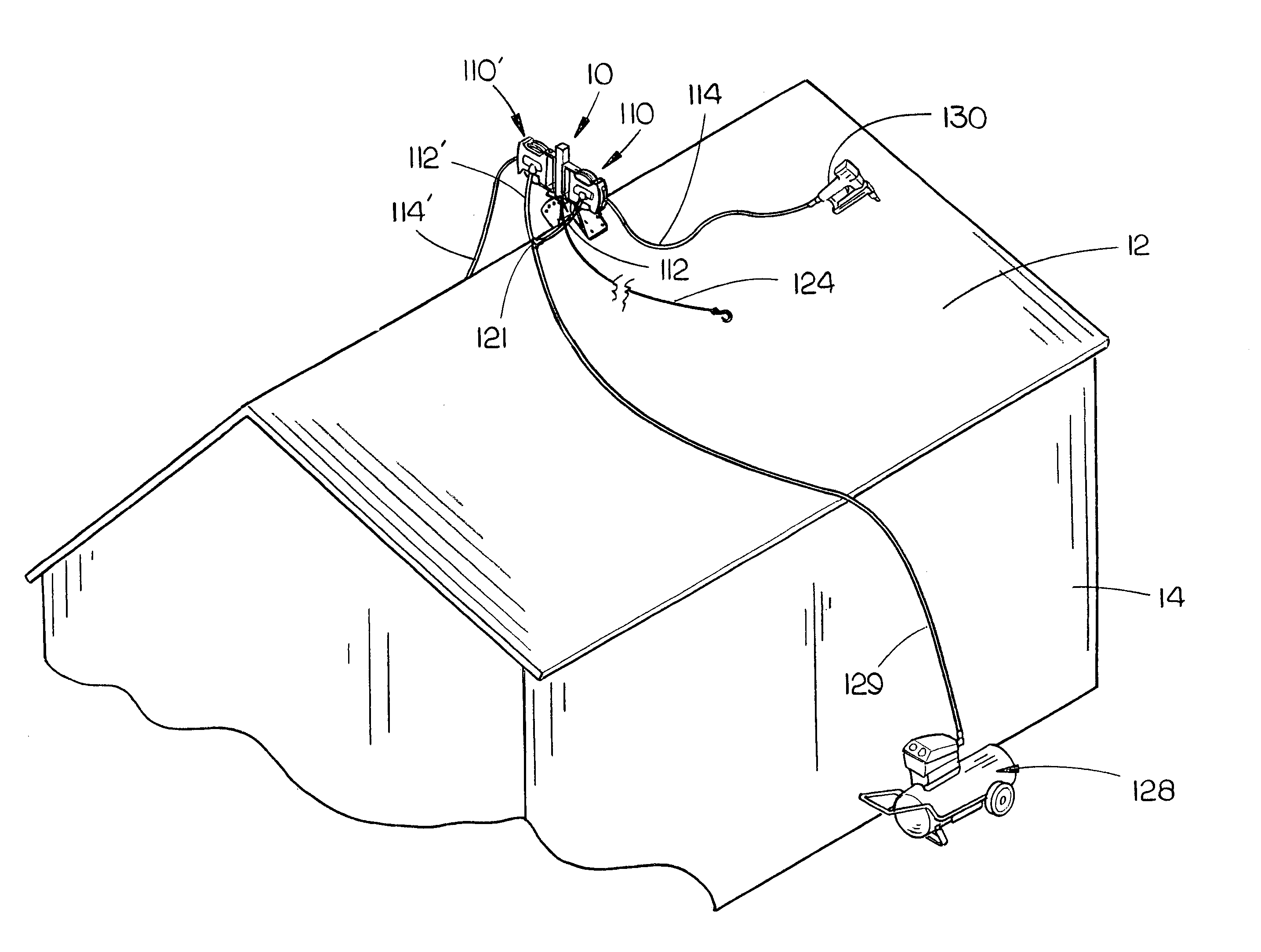
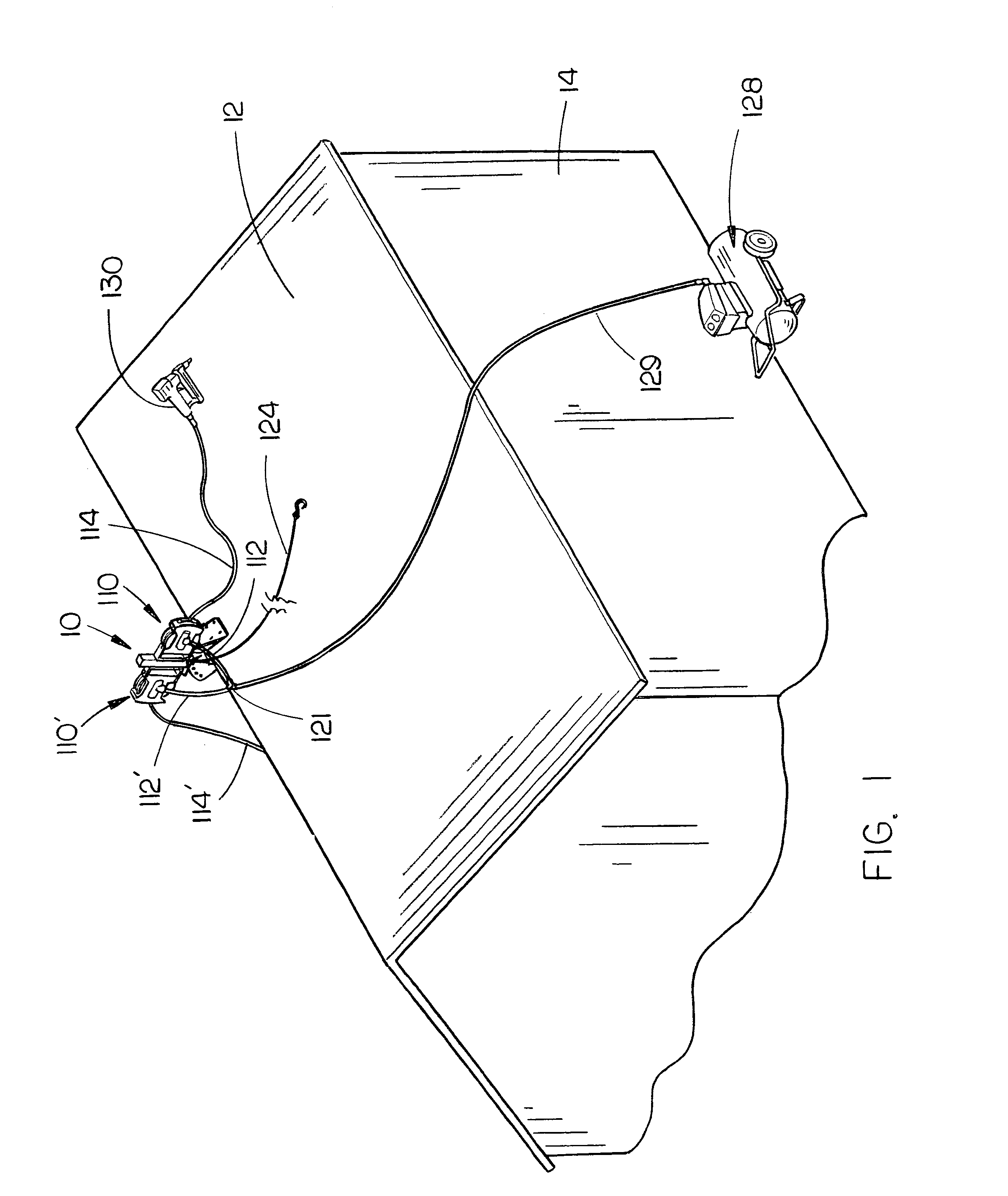
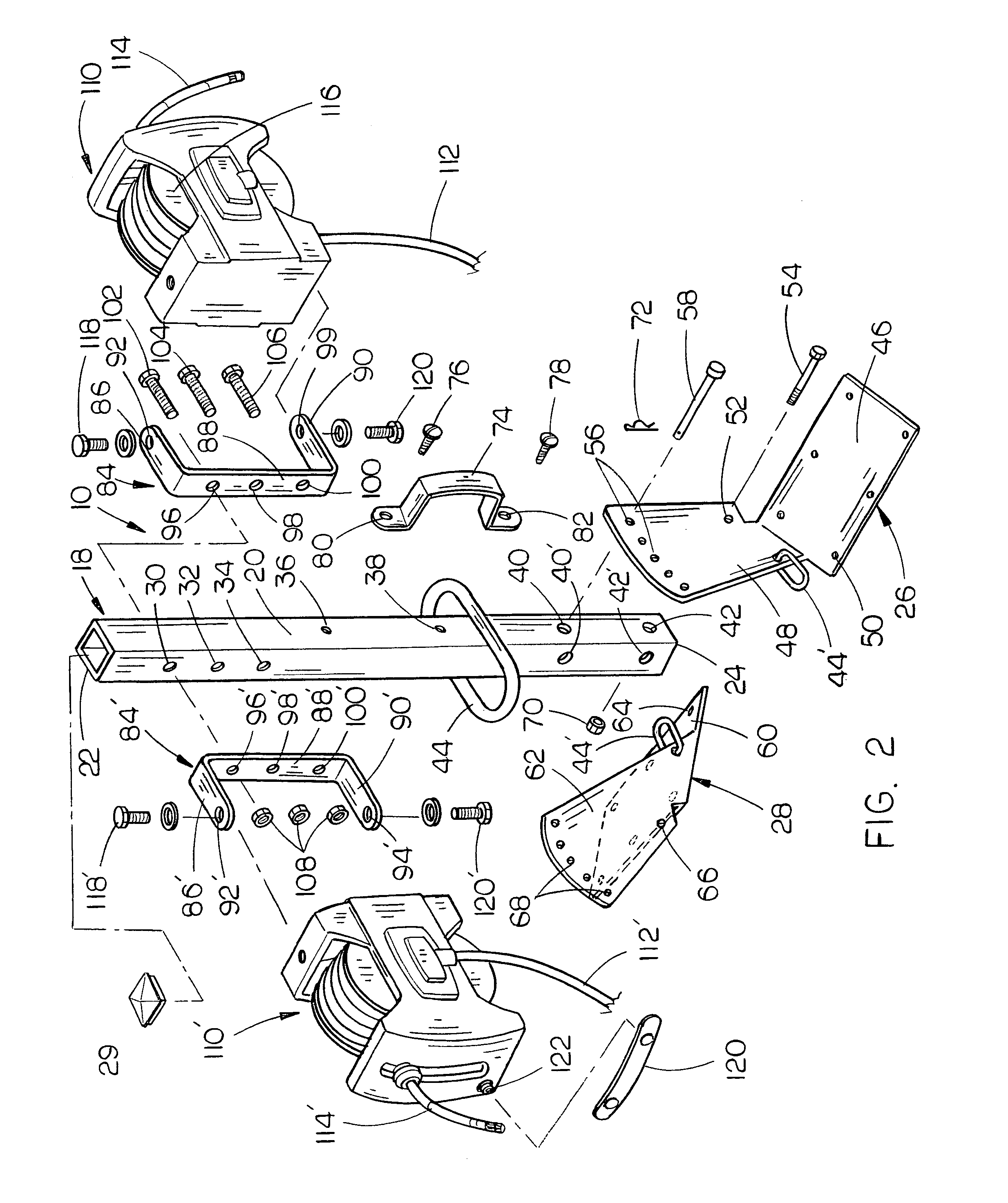
[0026]The roof mounted air hose holder of this invention is referred to by the reference numeral 10. Holder 10 may be mounted on the ridge 11 of a pitched roof 12, having different pitches, of a building 14 (FIG. 1) or on a flat roof 16 (FIG. 4). Holder 10 includes a roof bracket assembly 18 which is comprised of an upstanding post or tube 20, having an upper end 22 and a lower end...


PUM


Abstract

A roof mounted air hose holder is provided which is adapted to be mounted on roofs having different pitches. The air hose holder may also be mounted on a flat roof. In a modified form of the invention, one of the air hose reels of the air hose holder may be replaced by an electrical cord reel. In another embodiment, both of the air hose reels may be replaced by electrical cord reels.

Description

BACKGROUND OF THE INVENTION[0001]1. Field of the Invention[0002]This invention relates to an air hose holding device for use on a pitched roof having a ridge with first and second roof portions extending downwardly and outwardly from the ridge. More particularly, the air hose holding device of this invention includes a pair of air hose reels mounted on an upstanding post which may be attached to roofs having varying pitches. The invention also relates to an electrical cord holding device for use on either a flat roof or a pitched roof.[0003]2. Description of the Related Art[0004]The construction of a roof of a building normally involves the use of pneumatic tools such as nailers, etc. The pneumatic tools are connected to a source of air under pressure such as an air compressor by long air hoses. Since the roofs are normally pitched, it is difficult to maintain the hoses on the roof without them sliding downwardly to the ground taking the pneumatic tool with it. Further, if the air h...

Claims


Application Information

Patent Timeline
Patent Type & Authority Patents(United States)
IPC IPC(8): A47G29/02A62B1/16
CPCF16L3/012B65H75/40B65H75/446B65H75/4463B65H2701/33B65H2701/34Y10T137/6918Y10T137/6954
Inventor SCHINDLER, TERRENCE R.RIFE, NICHOLAS J.
Owner SCHINDLER TERRENCE R
Why Eureka
Try Eureka