Supercharge Your Innovation With Domain-Expert AI Agents!

Method and apparatus for video signal processing

a video signal and processing method technology, applied in signal generators with optical-mechanical scanning, color televisions with bandwidth reduction, etc., can solve the problems of human perceptible data errors, lossy compression forms, and certain amount of data permanently lost during the compression process, so as to improve the quality of video signals

Inactive Publication Date: 2012-10-23
CSR TECH INC
View PDF17 Cites 11 Cited by
  • Summary
  • Abstract
  • Description
  • Claims
  • Application Information

AI Technical Summary

Benefits of technology

"This patent describes a system and method for improving the quality of video signals by detecting and eliminating block boundaries and other artifacts. The system uses filters to selectively filter block boundaries and other artifacts while maintaining the non-filtered portions of the video signal. This results in a higher quality video signal. The method involves detecting potential block boundaries, determining an offset parameter for each pixel, and comparing the boundary verification value to a threshold to determine if the potential block boundary is an artifact. The system can also detect multiple potential block boundaries and perform a 2-dimensional gradient measurement to further confirm the presence of an artifact. Overall, this patent provides a technical solution for improving the quality of video signals by eliminating block boundaries and other artifacts."

Problems solved by technology

Some forms of compression can be lossy, and as such, a certain amount of data can be permanently lost during the compression process.
Due to this data loss, a reconstructed image based on the compressed signal may not be identical to the image as it existed prior to its compression and encoding.
Despite these efforts, compression of a video signal can still result in various unwanted compression artifacts and other humanly perceptible data errors.

Method used


Image

  • Method and apparatus for video signal processing
  • Method and apparatus for video signal processing
  • Method and apparatus for video signal processing

Examples


Embodiment Construction

[0024]The systems and methods described herein are not limited in their application to the details of construction and the arrangement of components set forth in the description or illustrated in the drawings. The invention is capable of other embodiments and of being practiced or of being carried out in various ways. Also, the phraseology and terminology used herein is for the purpose of description and should not be regarded as limiting. The use of “including”“comprising”“having”“containing”“involving” and variations thereof herein, is meant to encompass the items listed thereafter and equivalents thereof as well as additional items.

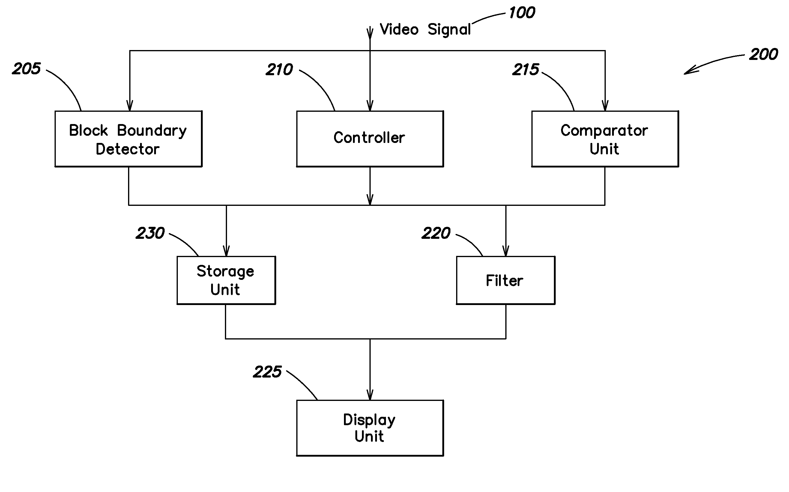
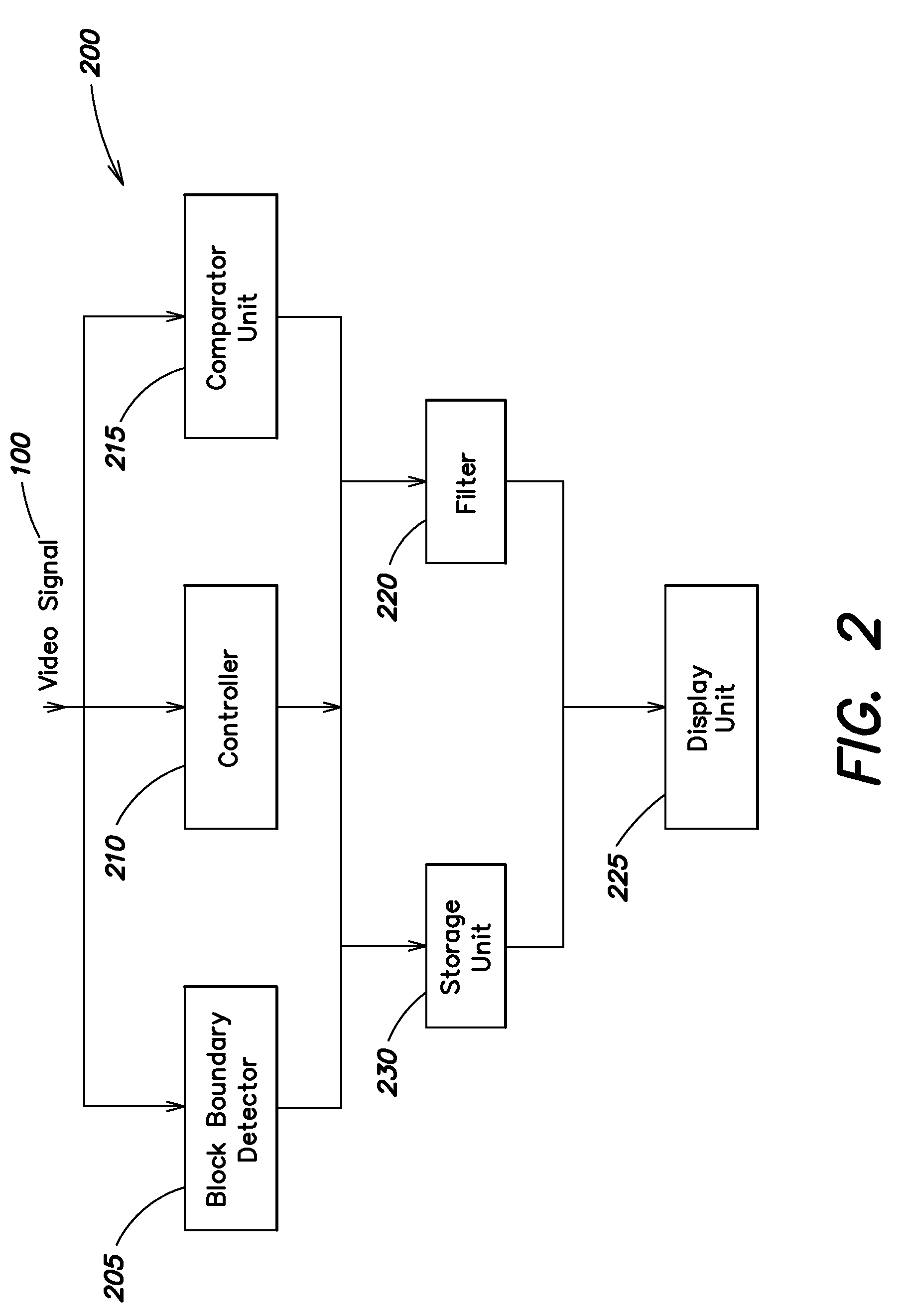
[0025]Various aspects and embodiments are directed to video signal processing. As discussed further below, frames of video signals can include a plurality of blocks. Lossy compression of data in the video signals can introduce visible artifacts, such as blocking artifacts, which appear as visually perceptible outlines between neighboring blocks in the ...


PUM


Abstract

Systems and methods of processing a video signal are provided. A potential block boundary can be detected between a first block and a second block of a frame of the video signal, wherein the frame, the first block, and the second block each include a plurality of pixels. An offset parameter can be determined for at least one pixel of at least one of the first block and the second block. Based on the offset parameter, a boundary verification value of at least one of the first block and the second block can also be determined. Based on the boundary verification value, it can further be determined if the potential block boundary includes a block boundary.

Description

CROSS REFERENCE TO RELATED APPLICATIONS[0001]This application claims priority under 35 U.S.C. 119(e) to U.S. Provisional Application Ser. No. 61 / 020,662 entitled “Method and Apparatus for MPEG Blocking Artifact Removal,” filed Jan. 11, 2008, which is incorporated herein by reference in its entirety.BACKGROUND OF THE INVENTION[0002]1. Field of Invention[0003]Aspects of the present invention are directed to processing of a video signal, and more particularly to a system and method for minimizing distortion in a video signal.[0004]2. Discussion of Related Art[0005]Digital video signals contain compressed data in order to conserve system resources such as bandwidth and memory. To do so, the images that constitute the video signal can be divided into a series of quadrilateral segments, referred to as blocks, where each block contains at least one pixel, ordered by row and column. The data in each of these blocks can be transformed into a matrix of coefficients. These coefficients are the...

Claims


Application Information

Patent Timeline
Patent Type & Authority Patents(United States)
IPC IPC(8): H04N7/12
CPCH04N19/176H04N19/61H04N19/86H04N19/14H04N19/117
Inventor TANG, MONICACESANA, JOSEPHMOVSHOVICH, ALEKSANDR
Owner CSR TECH INC
Features
  • R&D
  • Intellectual Property
  • Life Sciences
  • Materials
  • Tech Scout
  • Unparalleled Data Quality
  • Higher Quality Content
  • 60% Fewer Hallucinations
Learn More