
System and method for dynamically partitioning context servers

a dynamic partitioning and context server technology, applied in the field of system and method for dynamic partitioning context servers, can solve the problems of ineffective solution, inability to reliably identify the appropriate destination network control element and properly, and inability to ensure that a backup control element could take over and operate properly

Active Publication Date: 2012-10-23
VERISIGN
View PDF38 Cites 0 Cited by
  • Summary
  • Abstract
  • Description
  • Claims
  • Application Information

AI Technical Summary

Benefits of technology

The patent text describes a solution for reliably identifying and tying together call signals in a telecommunication network. The solution involves adding context servers to the network and accessing the servers to store and retrieve call signals and context information about previous calls. This allows network control elements to process current calls without needing to receive and process preceding calls. The solution provides a highly reliable network with redundant backup control elements that can process different call signals concurrently.

Problems solved by technology

As such, the intermediary routing node may not reliably identify the appropriate destination network control element and properly route all the call signals for the call thereto.
This solution, however, is not very efficient because several of the control elements are idle and are only used when there is a primary element failure, while the primary control element works constantly.
Moreover, after sitting idle, there is no guarantee that a backup control element could take over and operate properly, in the event of a primary element failure.
This solution, however, is also not very efficient because of the duplicated work by the control elements, such that the backup element's processing power is wasted when it could be used to process other call signals.
Moreover, the number of redundant control elements may be arbitrarily large.
However, in some instances, there may be no particular basis upon which the context servers are given responsibility, e.g., server capacity, sever utilization, network traffic, etc., which could then result in load imbalance.
Or, during network operation, a new network condition may occur that leads to network inefficiency, in which some or all of the context servers are either over-utilized or under-utilized.
Until the network condition changes, the context servers may operate inefficiently.

Method used


Image

  • System and method for dynamically partitioning context servers
  • System and method for dynamically partitioning context servers
  • System and method for dynamically partitioning context servers

Examples


Embodiment Construction

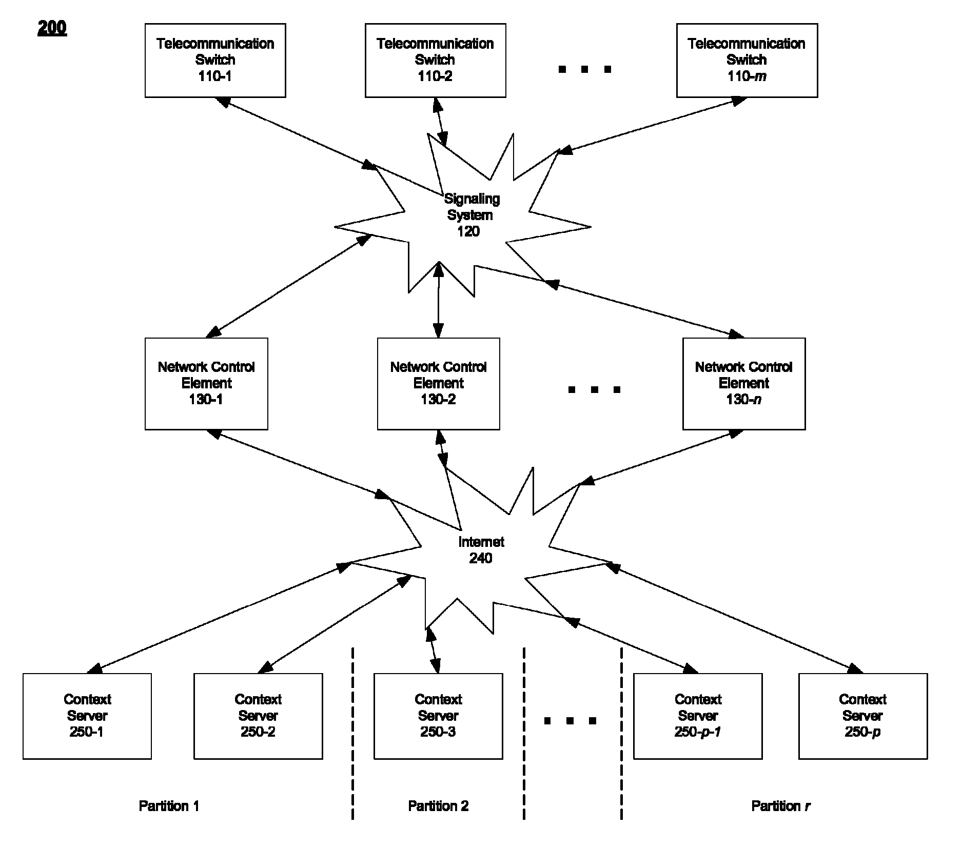
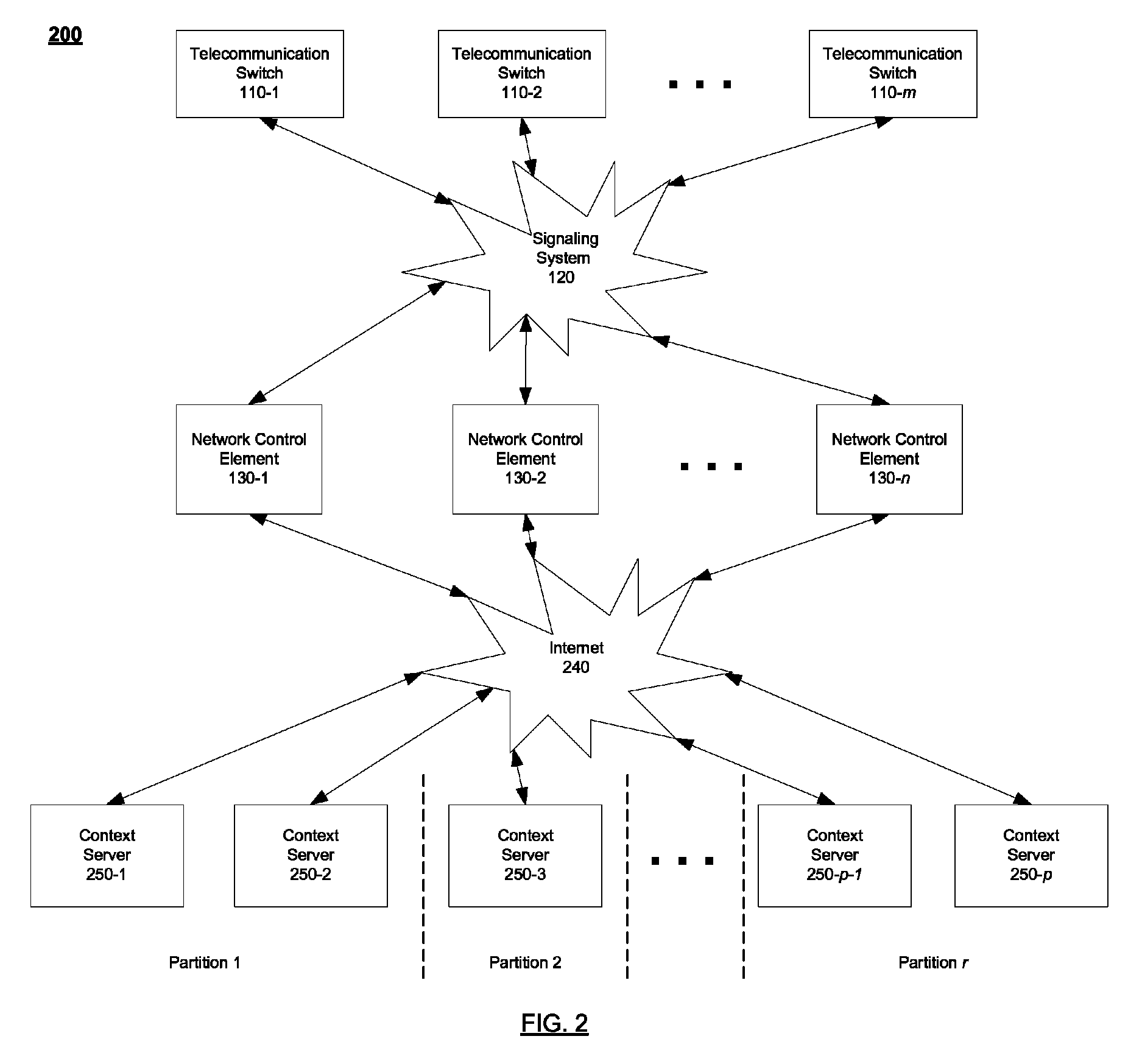
[0027]For a call signaling-based telecommunication network to operate efficiently, the network should be able to partition the context servers to respond to changes in network conditions that may result in inefficiency, e.g., high latency, high processor utilization, low memory space, bandwidth constraints, etc. To do this, according to embodiments of the present invention, during network operation, the network may dynamically partition the context servers. This can advantageously provide faster context information access, load balancing among the context servers, and reduced context information redundancy, thereby contributing to the high reliability of the network. All of the network's context servers need not store redundant information and network components need not have access to all of the context servers for context information.

[0028]Embodiments of the present invention are directed to dynamic context server partitioning in call signaling-based networks. The present inventio...


PUM


Abstract

A system and method for dynamically partitioning context servers in a network in response to changes in network conditions. Context servers store information about calls in a telecommunications system. Network control elements can obtain call information from one or more partitions of the context servers to help make call control and reporting decisions.

Description

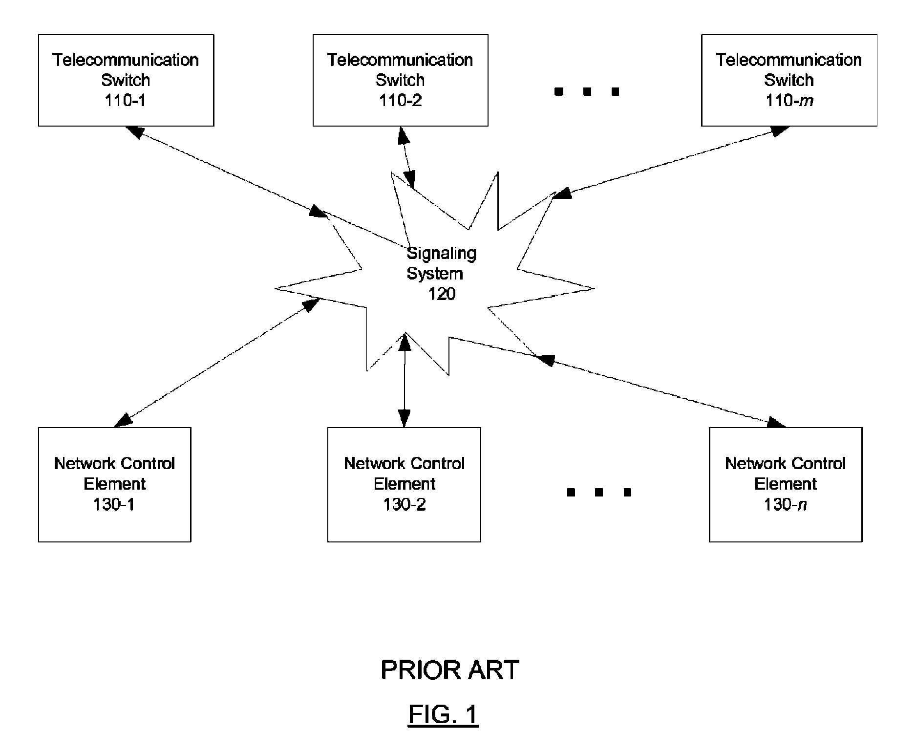
CROSS-REFERENCE TO RELATED APPLICATIONS[0001]This application is a continuation-in-part of U.S. patent application Ser. No. 11 / 509,037, filed Aug. 24, 2006,, the entire contents of which are incorporated herein by reference.BACKGROUND OF THE INVENTION[0002]Modern telecommunication networks provide services based on call signaling. The network signaling protocol includes a service layer upon which many of the provided services are implemented. Such services include 1-800 and toll free calling, calling cards, private virtual networks, cellular registration and roaming, prepaid calling, etc.[0003]FIG. 1 is a diagram of such a call signaling-based telecommunication network. The network includes one or more telecommunication switches 110-1 through 110-m, a signaling system 120, and one or more network control elements 130-1 through 130- n. The telecommunication switches 110 are responsible for connecting and disconnecting a telephone call and are primary originators of call signals (or c...

Claims


Application Information

Patent Timeline
Patent Type & Authority Patents(United States)
IPC IPC(8): H04M15/00
CPCH04Q3/0029H04Q2213/13103H04Q2213/13106H04Q2213/13134H04Q2213/13164H04Q2213/13166H04Q2213/13167H04Q2213/13345
Inventor GALLANT, JOHN KENNETH
Owner VERISIGN
Learn More