Method and system for monitoring a wireless communications network

a wireless communication network and wireless communication technology, applied in the field of wireless telecommunications systems, can solve the problems of call quality decline, call loss, and increased likelihood of interference between mobile stations, and achieve the effects of convenient mounting, improved mdm arrangement, and convenient central analysis and reporting

Inactive Publication Date: 2005-07-05
SPRING SPECTRUM LP
View PDF12 Cites 147 Cited by
  • Summary
  • Abstract
  • Description
  • Claims
  • Application Information

AI Technical Summary

Benefits of technology

[0013]In response to instructions from the computer, for instance, MS-1 may periodically or continuously report diagnostic data to the computer. As the computer receives that diagnostic data, the computer may also receive location data indicating the location of MS-1. As the computer receives the diagnostic and location data, the computer may cause MS-2 to transmit the data, via the wireless network, to a central server (e.g., at a central office, for instance). Finally, as the data arrives at the server, the server may compile and map out the data (e.g., by location), thereby facilitating substantially real-time reporting and management of network conditions.
[0014]Advantageously, this improved MDM arrangement can be controlled and managed from a remote site, such as from the central server for instance. A technician at the remote site can cause

Problems solved by technology

For instance, as the level of call traffic increases in a typical cell site, the likelihood of interference between mobile stations can increase substantially.
With lower transmission power, however, call quality can diminish, and calls may ultimately be lost.
As a result of new or changed s

Method used


Image

  • Method and system for monitoring a wireless communications network
  • Method and system for monitoring a wireless communications network
  • Method and system for monitoring a wireless communications network

Examples


Embodiment Construction

1. Exemplary Architecture

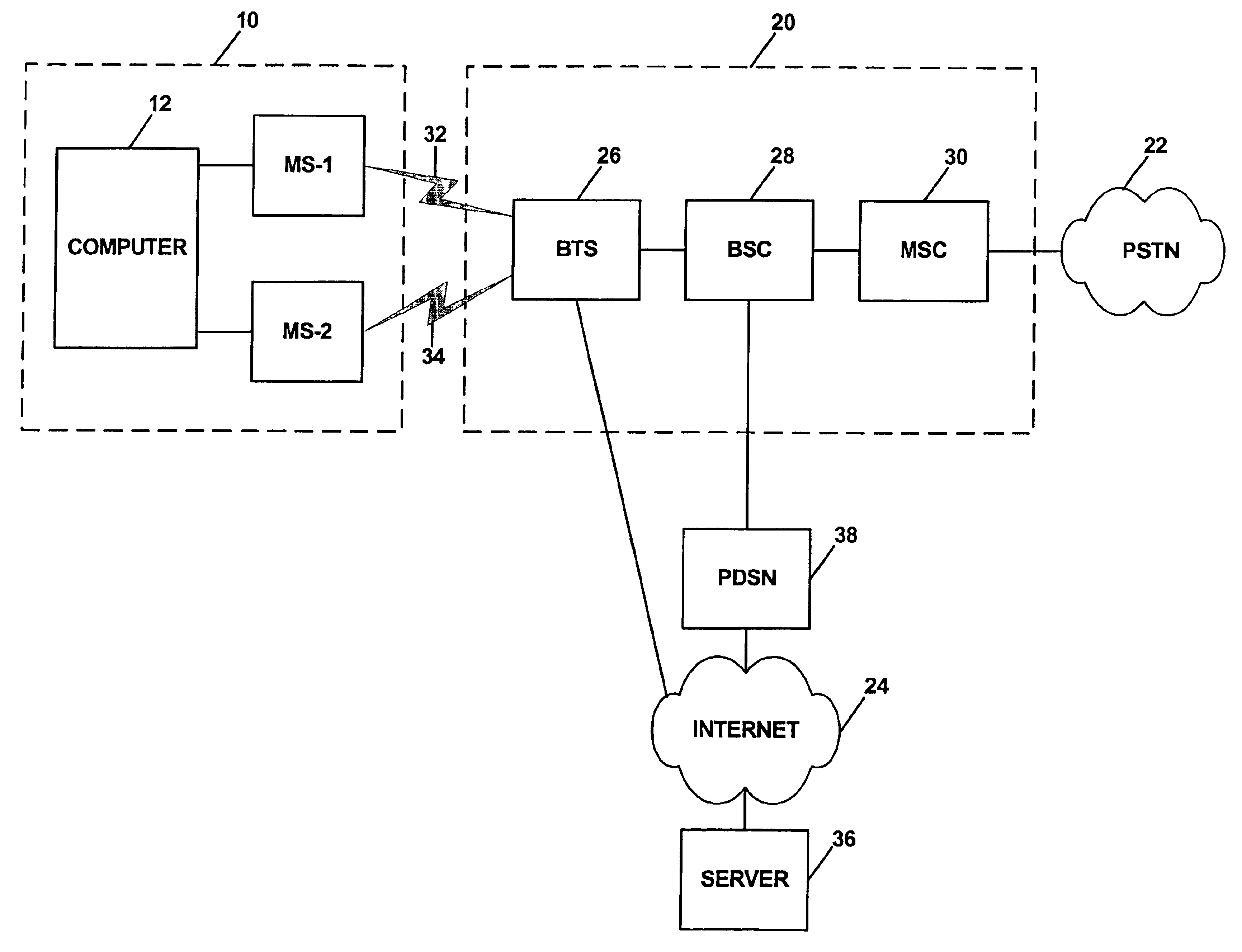
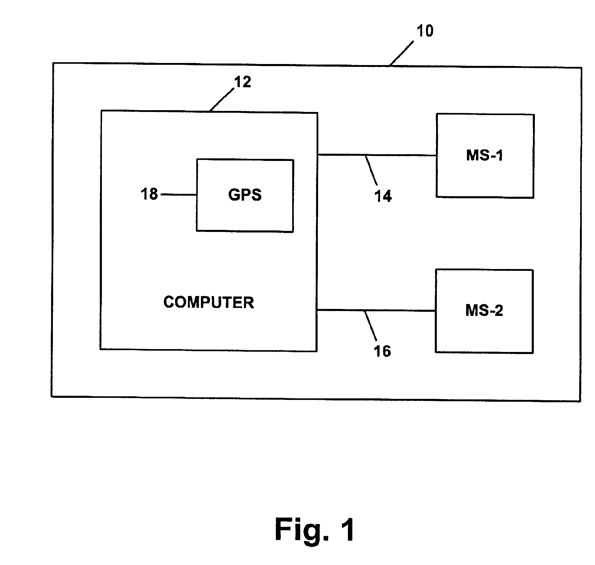
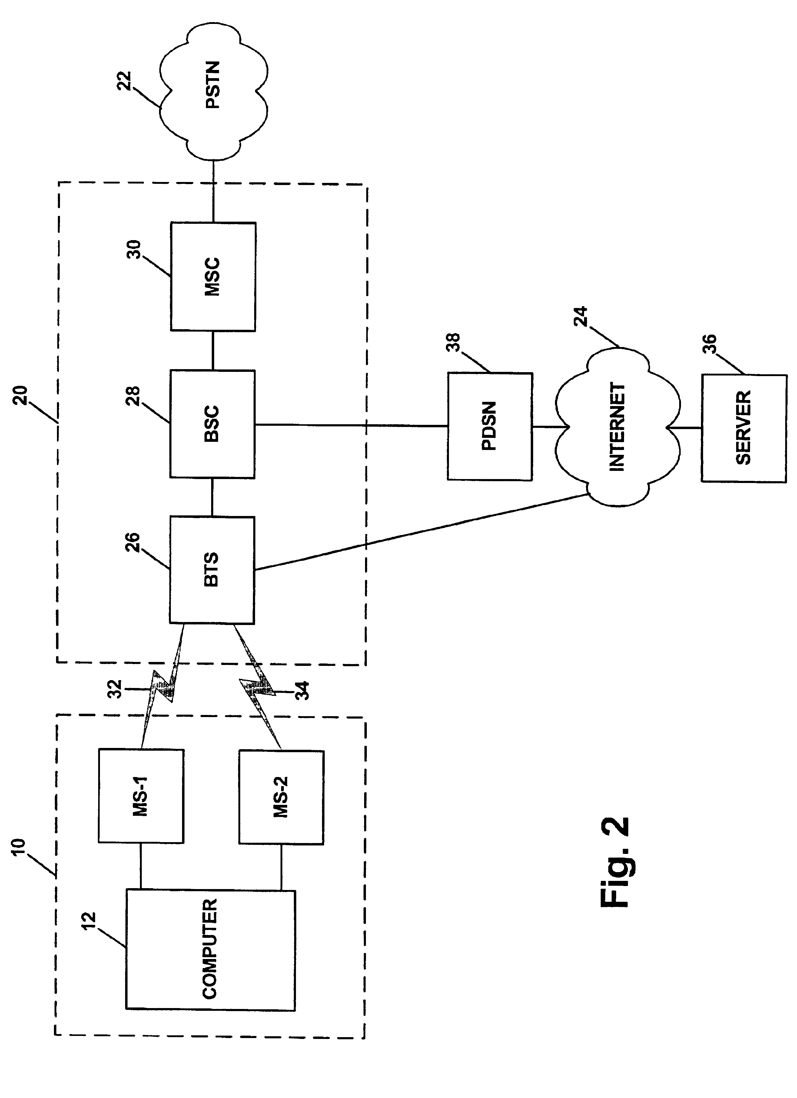
[0022]Referring to the drawings, FIG. 1 is a simplified block diagram illustrating an MDM system 10 arranged in accordance with an exemplary embodiment of the present invention. As shown in FIG. 1, system 10 includes a first mobile station MS-1, a second mobile station MS-2, and a computer 12. MS-1 may be communicatively coupled with computer 12 by a link 14, and computer 12 may be communicatively coupled with MS-2 by a link 16. In this arrangement, MS-1 can provide information to computer 12 via link 14, and computer 12 can provide information to MS-2 via link 16.

[0023]As further illustrated, computer 12 preferably includes or is in communication with a location determining mechanism 18 that allows computer 12 to determine a position of MS-1. Location determining mechanism 18 may most conveniently be a global positioning system (GPS) transceiver, the arrangement of which is well known to those skilled in the art and therefore not described here. Alternative...


PUM


Abstract

A method and system for monitoring wireless network conditions. Two mobile stations are coupled with a computer. The first mobile station interacts with the network and thereby establishes diagnostic data concerning network conditions. The first mobile station then reports that diagnostic data to the computer. As the computer receives the diagnostic data from the first mobile station, the computer obtains location data indicative of the current location of the first mobile station. The computer then provides the diagnostic data and corresponding location data to the second mobile station, which in turn transmits the data to a remote entity via the wireless communications network. As the remote entity receives the data, the remote entity may generate output reports and alerts as desired. Conveniently, the combination of the mobile stations and computer may be mounted in a vehicle and carried around a geographic area, so as to automatically report diagnostic data to the remote entity from a variety of locations.

Description

BACKGROUND[0001]1. Field of the Invention[0002]The present invention relates to wireless telecommunications systems and, more particularly, to monitoring and reporting of network conditions in such a system.[0003]2. Description of Related Art[0004]In a cellular radio communications system (wireless communications network), an area is divided geographically into a number of cell sites, each defined by a radio frequency (RF) radiation pattern from a respective base transceiver station (BTS) antenna. The BTS antennae in the cells are in turn coupled to a base station controller (BSC), which is then coupled to a telecommunications switch or other gateway, thereby facilitating communication with a telecommunications network such as the PSTN (public switched telephone network) or the Internet.[0005]When a mobile station (such as a cellular telephone, pager, or appropriately equipped portable computer, for instance) is positioned in a cell, the mobile station communicates via an RF air int...

Claims


Application Information

Patent Timeline
IPC IPC(8): H04Q7/34H04W24/00
CPCH04W24/00
Inventor OH, DAE-SIK
Owner SPRING SPECTRUM LP
Why Eureka
Try Eureka