Methods and apparatus for utilizing electrically powered vehicles

a technology of electrically powered vehicles and methods, applied in the direction of tractors, cycle equipment, cycles, etc., can solve the problems of limiting the speed of the system, exacerbate the wear of the brush, and provide a higher speed range with poor starting torque and acceleration

Inactive Publication Date: 2012-10-30
EV IP
View PDF54 Cites 35 Cited by
  • Summary
  • Abstract
  • Description
  • Claims
  • Application Information

AI Technical Summary

Problems solved by technology

While electric vehicles may be gaining in popularity, many aspects of electric vehicle technology still may carry drawbacks capable of improvement.
A challenge with electric vehicles may be the gearing trade off.
Using only low gearing may limit the speed of the system once the torque requirements are fulfilled.
High gearing (motor spins not as fast to achieve the same wheel speed) may provide higher speed range with poorer starting torque and acceleration.
High gearing may also stress a motor more when starting, because low rpm high electric currents may be sustained longer and may heat up the windings and perhaps exacerbate brush wear.
Fewer motor revolutions over a distance traveled also may prolong motor life.
Such a system may be relatively complex and mechanical in design.
In cars, manual shifting may have been removed with automatic transmissions, but the elimination of manual shifting may result in more complex controls and coupling apparatus.
These kits may include conventional throttles which may mount on handle bars, perhaps sometimes requiring removal of rubber grips to slide over the handle bar, or perhaps using a thumb lever that may be ergonomically challenging with gear shifters, or possibly not fitting well around handle bar extensions.
These kits may require time and skill to install on a bicycle and may not be made to be quickly moved from one bicycle to another.
A problem may be that bicycle handle bars may host a wide variety of grips, handle bar extensions, bells, lights, brake levers, and gear shifters (twist, thumb and finger, thumb only, and brake lever actuated).
Adding yet another function to the hand area may be physically constrained and ergonomically challenging.
Making a simple throttle that can work on a multitude of bicycle designs may be even more challenging.
Products like bicycle conversion kits and powered trailers may create an unanswered need.
A hitch design that only works for a few bicycle styles may limit sales, while a design that fits many bicycles may expand sales.
Analogous features in a throttle design may be lacking in conventional bicycle designs.
Conventional designs may include: (1) twist throttles, which typically may require removal of rubber grips to provide a bare bar for sliding the throttle over the end and fastening with screw—these may not work with twist shifters and curved handlebars; and (2) thumb lever switches that may fit over round handle bars and may fasten with a screw or two—these may not be compatible with thumb shifters, because there may be two thumb levers in a crowded space.
Thumb actuators, when placed on a bicycle with thumb shifters, may either conflict with the gear shifter or may make one of the thumb devices more difficult to use.
They may not work well at all with twist gear shifters.
The twist grip actuator may require removal of the handlebar grip for installation, and also may not work in tandem with a twist gear shifter.
A distinct challenge of electric vehicles may emerge from the use of electric parts and assemblies in addition to normal mechanical parts like wheels, chains, gears and brakes.
Effective technicians well versed in both electronics and mechanics may be rare, and so troubleshooting and repair of malfunctioning electric vehicles may be rarely sufficient for owners and service centers.
While sales of electric vehicles may have increased over the last few years, home mechanics and bicycle shop mechanics may not necessarily have the skills and tools to deal with these products.
Methodical troubleshooting guides may be rarely available and may be of little help to those not trained in basic electronics.
When an electric vehicle stops functioning, nominally skilled owners and shop mechanics may not know if the problem is a bad battery, broken wire, or worn out motor.
Many owners may be stuck with no easy way to get help.
Units may be discarded prematurely out of frustration and further purchases may be delayed or dismissed.
Many consumers may choose to not buy an electric vehicle when they discover that they may require days to repair.
Some electric bicycles may provide error codes for a few components when there is a hard failure.
Electric bicycles and other similar vehicles may be more complex, with multiple interactive parts like motors, batteries, controllers, throttles, and other elements.
Swapping parts often may be difficult, expensive, and slow, because such parts often may be more integrated into the unit.
And sometimes a component may work well on the bench (not having to push a rider and bicycle) and may not perform well on the road.
Swapping parts and road testing may be laborious and even more time consuming.
No Trouble Found (“NTF”) may be an expensive and frustrating issue in the service business.
Intermittent failures, like a wire with damaged insulation infrequently touching metal, may lead to NTF when the service technician tests the unit while the wire is not touching metal.
When a product fails and the customer brings it in for repair, and then it works fine once the repair technician sees it, then the technician may have no idea what is wrong and the customer may be vulnerable to it failing again.
Repeated instances of this may be especially difficult.
These problems often may lead to expensive repairs that may not be required, and may leave the unit in a state of intermittent functionality.
The issue may continue inefficiencies, because the factory may receive replaced parts that are not failed and may not be able to identify the right issue to redesign.
Local bicycle shops whose customers bring in electric bicycles or scooters may either call in a qualified technician, train an employee, or have to deny service to the customer for fear of disappointing them.
Bicyclists oft may need to carry things with them, and these things can be of notable volume or weight.
Conversely, however, a trailer designed for carrying cargo may be unsafe to use to carry children.
While implementing elements may have been available, actual attempts to meet this need may have been lacking to some degree.
This may have been due to a failure of those having ordinary skill in the art to fully appreciate or understand the nature of the problems and challenges involved.
As a result of this lack of understanding, attempts to meet these long-felt needs may have failed to effectively solve one or more of the problems or challenges here identified.

Method used


Image

  • Methods and apparatus for utilizing electrically powered vehicles
  • Methods and apparatus for utilizing electrically powered vehicles
  • Methods and apparatus for utilizing electrically powered vehicles

Examples


example 1

Summary

[0105]The purpose of this Example 1 may be to improve upon electric bikes and trailers to provide perhaps more torque for acceleration or hill climbing while additionally enabling perhaps higher speed operation. These improvements may not add complex gear changing mechanisms and associated maintenance and decreased reliability.

[0106]This Example 1 may provide higher torque for starting or hill climbing and higher speed.

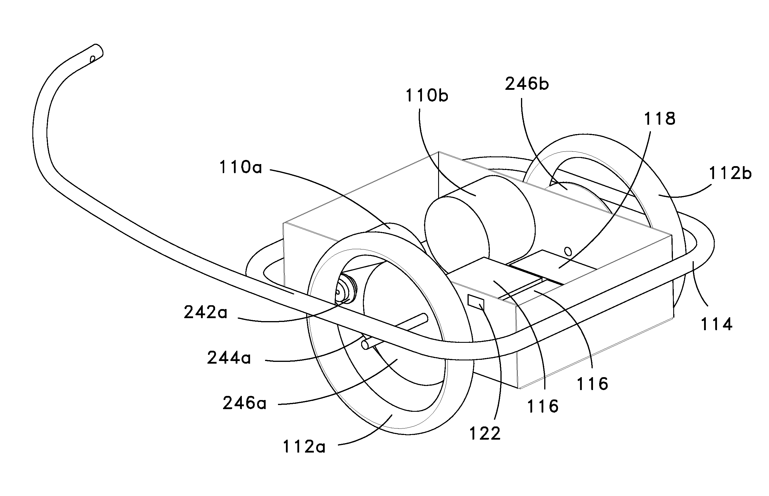
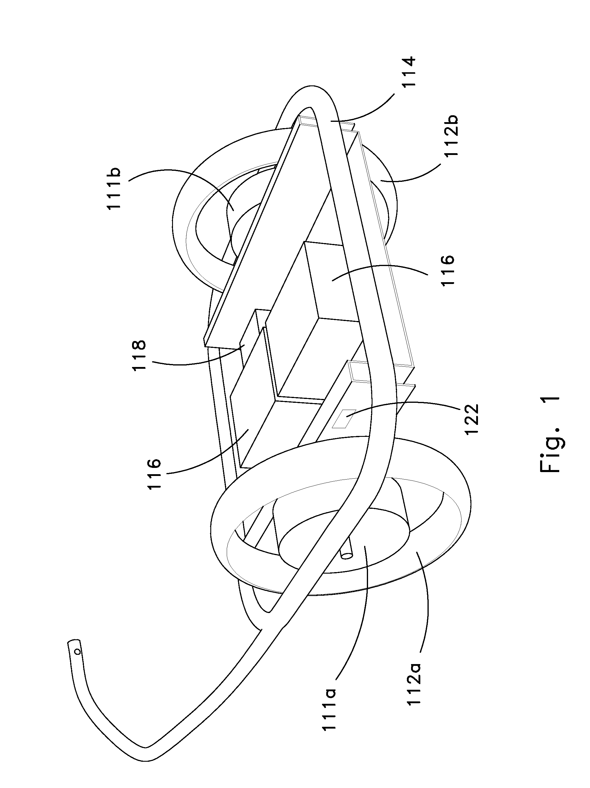
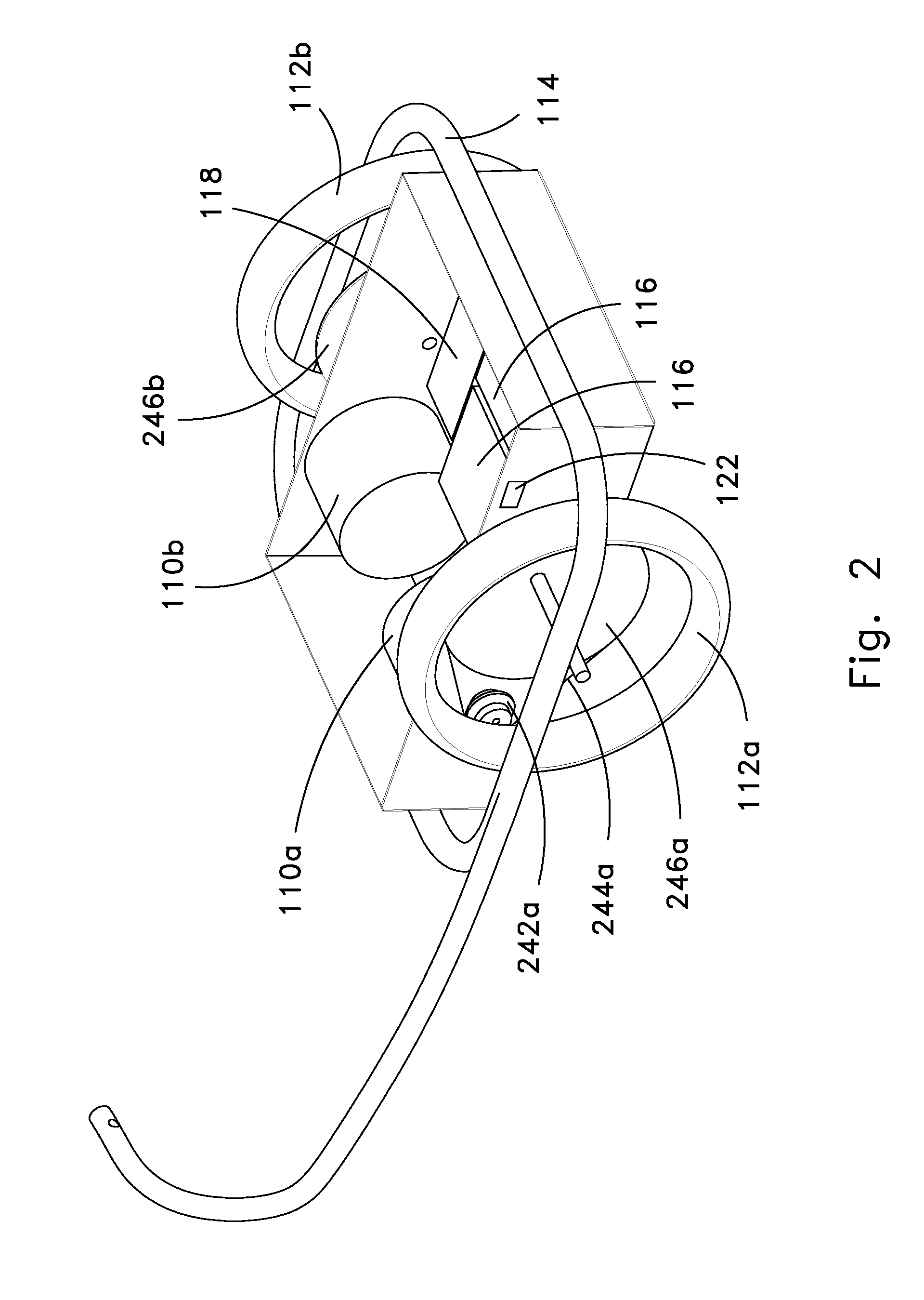
[0107]An improvement of the multi-wheeled electric bike, motorcycle, or trailer, may be accomplished with a motor for each wheel. A motor may be connected to one of the wheels and may be configured with low gearing for stronger startup torque. Another motor may be connected to a different wheel and may be configured with higher gearing for higher top speed. A controller may be used to shift power from one wheel to another based on torque, speed, throttle position, and / or other parameters which may indicate a trade between need for acceleration or higher speed.

[...

example 2

Summary

[0135]The purpose of this Example 2 may be to provide a throttle: 1) for an electric cycle or cycle with attached power trailer which a rider can actuate to command power from the motor; 2) that can be installed on a wide variety cycles quickly and simply (wide variety includes mountain bike style, cruiser style, recumbent style, and racing style wrap handlebars); 3) that can be moved or transferred from cycle to cycle quickly and simply; 4) that is mechanically and ergonomically compatible with various handbrakes, gear shifters, hand grips, and handle bar extensions or bar ends; and 5) a throttle that it is simple to use, adjustable for many size hands and fingers, ergonomically comfortable, and reliable.

[0136]This Example 2 may relate to a throttle that installs with no tools or minimal tools. One embodiment simply wraps around the grip and is held in place with Velcro or a clip. Another embodiment simply inserts into the hollow end of the handle bar. Both embodiments can b...

embodiment (

b)

[0163]Shown in FIG. 14, FIG. 15, and FIG. 16, bar insert 340 serves as a foundation for the throttle parts and coupling to the handle bar. Bar insert 340 has a slot and opening for the lever 342 which is held in place with pivot pin 346. Lever 342 is free to rotate around pivot pin 346 between the handle bar 360 and the maximum rotation constrained by interference between insert bar 340 and lever 342. Torsion spring 348 provides return force to lever 342 such that when the rider releases pressure from the lever 342, it springs outward to diminish the control signal. When released by the rider, the lever 342 springs all the way out to create an “off” signal. Buttons A and B 326 are mounted to the bar insert 340 to hold them in securely in place and alignment to lever 342. Buttons 326 are on top and bottom of lever 342. Lever 342 has raised cams that activate or depress the buttons 326 in sequence as the lever 342 is rotated around pivot pin 346 towards the handle bar 360. The motio...


PUM

PropertyMeasurementUnit
speedaaaaaaaaaa
speedaaaaaaaaaa
voltageaaaaaaaaaa

Abstract

Methods and apparatus may augment the utility of an electrically powered vehicle. A first electric motor (110a or 111a) may be provided with a first effective gear ratio, a second electric motor (110b or 111b) may be provided with a second effective gear ratio, and additional electric motors may be provided additional effective gear ratios. An electrically powered vehicle may be differentially powered by said electric motors at said different effective gear ratios. A transdisciplinary electrical diagnostic processor (440) may process electrically recondite operation parameters of one or more electrical components to provide transdisciplinary diagnostic output to a user. A standardized modular interface (540) supported on a trailer chassis (510) may be configured to accept multipurposed modular interchangeable trailer tops (560) at an interchange position (550) of said trailer chassis (510). A hand actuated accessory mount may be provided with a quick release interface (322).

Description

CROSS REFERENCE TO RELATED APPLICATIONS[0001]This application is a continuation of International Application No. PCT / US2010 / 035478, filed May 19, 2010, which claims priority to and the benefit of U.S. Provisional Application No. 61 / 179,536, filed May 19, 2009, and U.S. Provisional Application No. 61 / 180,846, filed May 23, 2009, and U.S. Provisional Application No. 61 / 250,863, filed Oct. 12, 2009, each said patent application and any priority case hereby incorporated herein by reference in their entirety.TECHNICAL FIELD[0002]Generally, the inventive technology relates to utilizing electrically powered vehicles. More particularly, the inventive technology involves novel methods and apparatus for optimizing the torque and speed delivered by electric motors, diagnosing electrical faults, utilizing interchangeable trailer tops, and providing quick release throttles and related accessories. The inventive technology may be particularly suited to providing supplemental electrical power to b...

Claims


Application Information

Patent Timeline
Patent Type & Authority Patents(United States)
IPC IPC(8): B62D59/04
CPCB62K27/003B62M7/16B62D59/04B60K26/04Y10T29/49826Y10T74/20396Y10T29/49002
Inventor WANGER, MARK E.ANDERSON, MARK A.
Owner EV IP
Why Eureka
Try Eureka