Male connector and connector apparatus

a male connector and connector technology, applied in the direction of coupling contact members, coupling device connections, securing/insulating coupling contact members, etc., can solve the problems of large connectors, complex construction of the fit-on part, and operator carelessly touching the male terminal fittings and receiving electrical shocks, so as to prevent the elastic deformation of the lance, avoid the increase of the number of components, and hold high strength

Active Publication Date: 2012-10-30
SUMITOMO WIRING SYST LTD
View PDF6 Cites 38 Cited by
  • Summary
  • Abstract
  • Description
  • Claims
  • Application Information

AI Technical Summary

Benefits of technology

[0009]The insulating coating on the front end of the male terminal fitting is formed by molding the resin, and hence is held on the male terminal fitting at a much higher strength as compared with a conventional construction in which the insulator is attached to the front end of the male terminal fitting. Thus, the insulation function is not likely to be damaged by foreign matter or an external force. Additionally, molding the resin to form the insulating coating part does not take much time or labor and facilitates quality management, as compared with an insulator mounted on the front end of the male terminal fitting.
[0010]The insulating coating part formed on the front end of the male terminal fitting eliminates the need for the housing to have a prevention rib projecting from the inner periphery of the tube to prevent a hand from contacting the terminal fitting. Therefore, the connector is simplified, smaller and less expensive.
[0012]A groove may be formed on a portion of the male terminal fitting covered with the insulating coating part. Accordingly, the effect to be obtained by molding the resin in a uniform thickness along the surface of the male terminal fitting is similar to the effect to be obtained by forming the groove and molding the insulating coating part.
[0014]The invention also relates to a connector apparatus having the above-described male connector and a female connector to be fit on the male connector. The female connector has a fit-on part with a cavity and a female terminal fitting accommodated in the cavity. A lance is disposed in the fit-on part and locks the female terminal fitting in the cavity. The lance can deform elastically inside a flexibility allowance space to unlock the female terminal fitting. The guide rib of the male connector preferably penetrates into the flexibility allowance space of the female connector when the male and female connectors are fit together and prevents the lance from elastically deforming. Thus the female terminal fitting is locked doubly and can be held at a high strength.
[0015]The lance will be deformed and will project into the flexibility allowance space if the female terminal fitting is not inserted sufficiently into the cavity. Thus, the guide rib will contact the lance when the female and male connectors are being fit together and will prevent complete connection. Therefore, an operator immediately can detect that the female terminal fitting is in a locking-inadequate state. The guide rib on the male connector performs a guiding function when fitting the female and male connectors together. The guide rib is formed unitarily with the male housing and avoids an increase in the number of component parts while making the entire connector apparatus compact.

Problems solved by technology

Thus when the female connector is removed from the male connector, there is a fear that an operator carelessly touches the male terminal fitting and receives an electrical shock.
Consequently the fit-on part has a complicated construction or the connector is large due to a spatial restriction.
Thus the construction is unreliable.

Method used


Image

  • Male connector and connector apparatus
  • Male connector and connector apparatus
  • Male connector and connector apparatus

Examples


Embodiment Construction

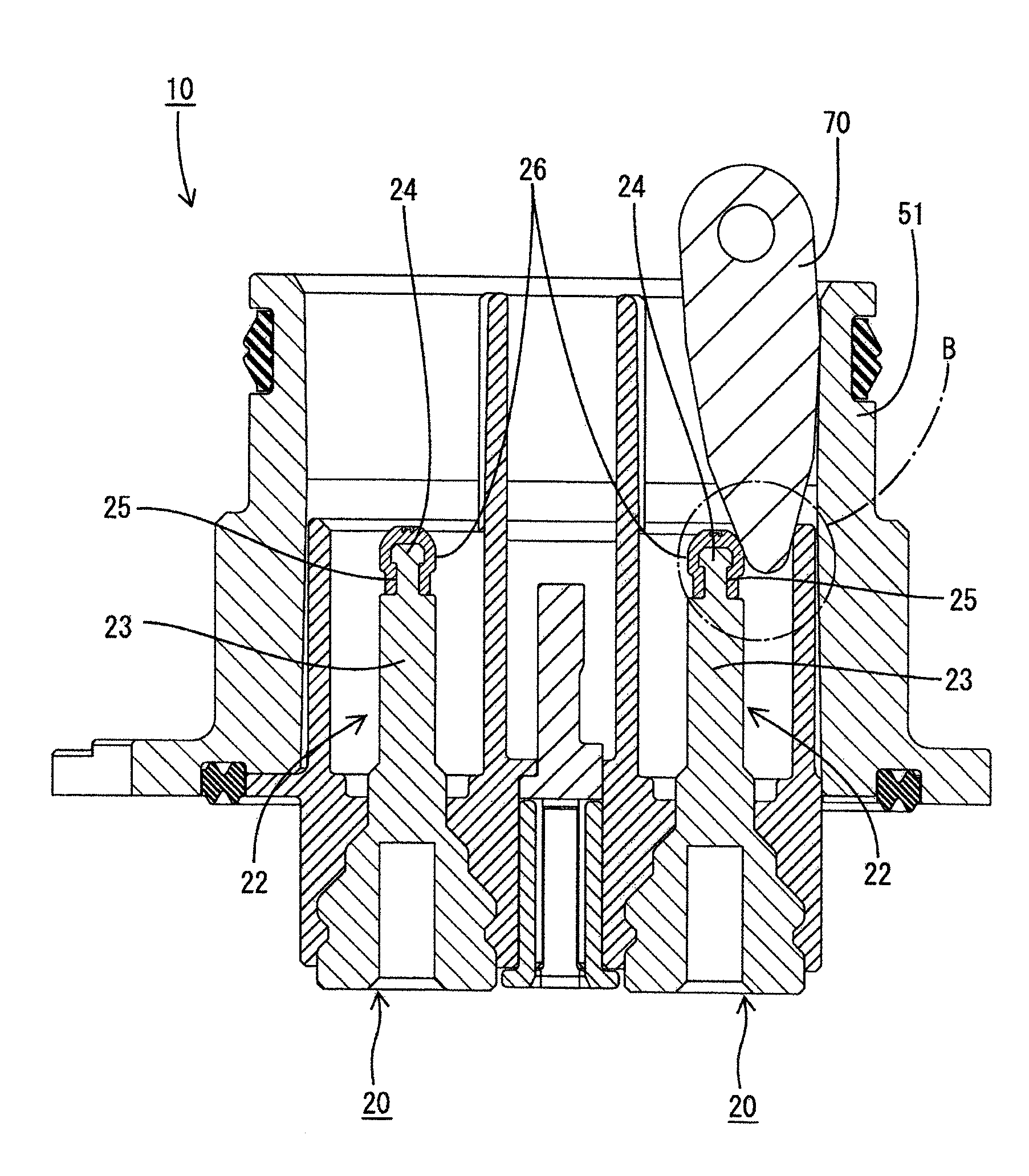
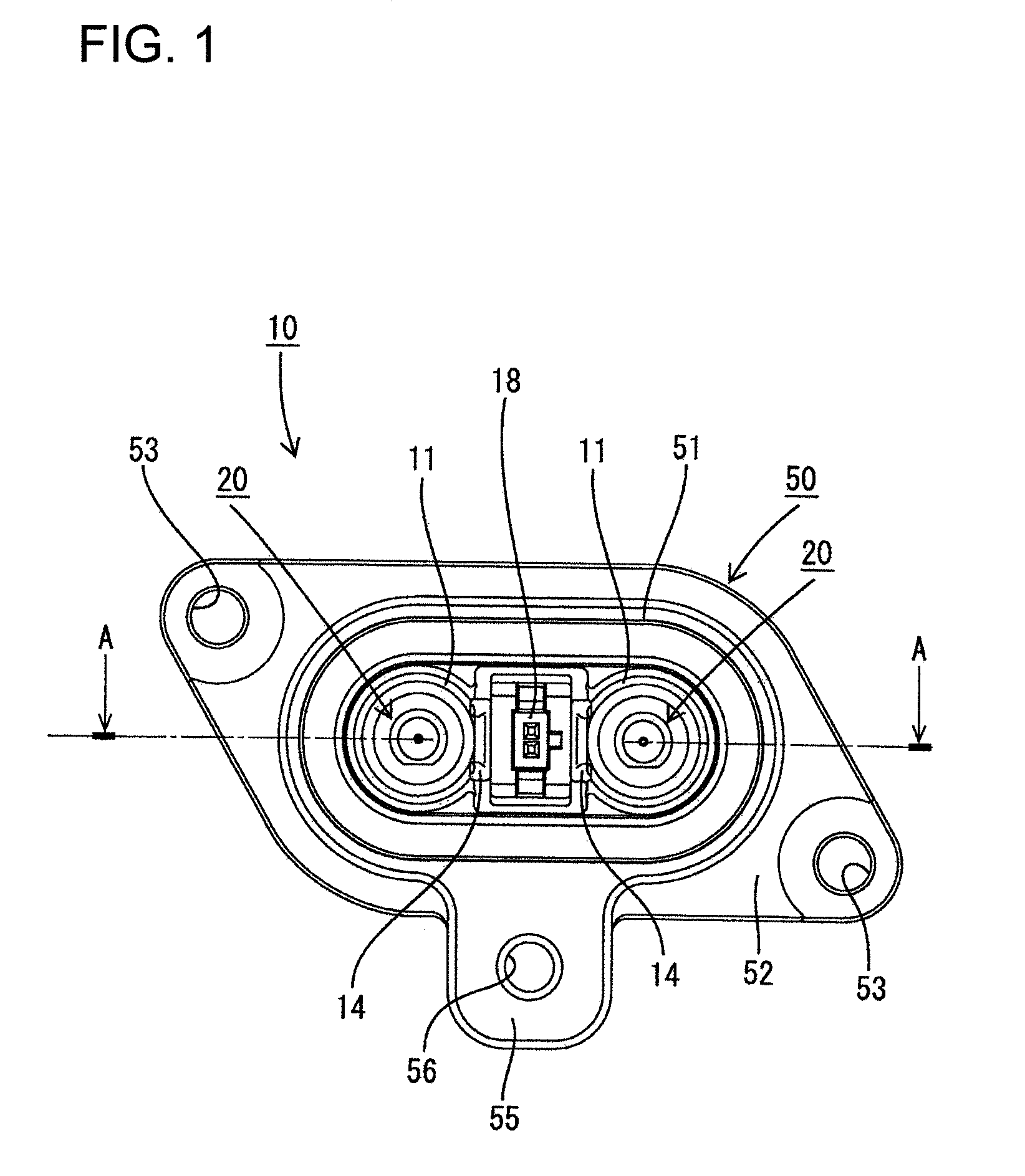
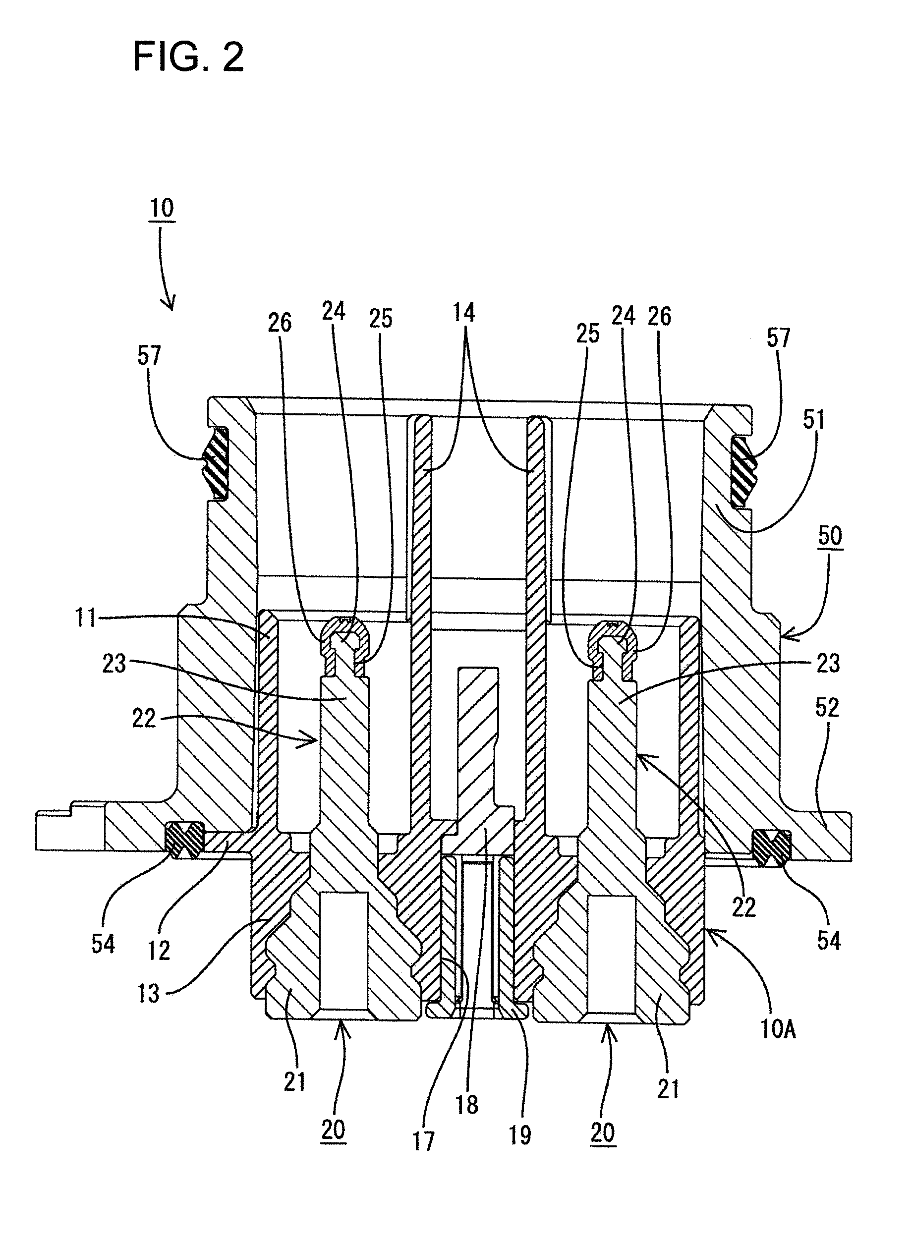
[0023]A connector apparatus in accordance with the invention is illustrated in FIGS. 1 through 10 and is exemplified as a connector for supplying an electric power to equipment mounted on a car (for example, motor, inverter, and the like mounted on hybrid car). The connector apparatus has a male connector (see FIG. 2) 10 to be fixed to the equipment and a female connector 30 (see FIG. 5) that can be fit on the male connector 10. In the following description, the fit-on ends of the male and female connectors 10 and 30 are referred to as the front. The equipment has an unshown metal case to perform a shielding function and an unshown connector-mounting hole penetrates through the case.

[0024]The male connector 10 has a male housing 10A made of synthetic resin. Tubes 11 are formed in the male housing 10A, as shown in FIG. 2, and define fit-on spaces for receiving parts of the female connector 30 as described later. A plate-shaped flange 12 projects out from a rear end of the tubes 11 an...


PUM


Abstract

A male connector (10) has a male terminal fitting (20) mounted in a male housing (10A). The male housing (10A) has tube (11) surrounding the male terminal fitting (20). The tube (11) is spaced out from a conductive part (23) of the male terminal fitting (20) by a distance so that a finger cannot be inserted between the tube (11) and the male terminal fitting (20). A fit-on part (31) of a female connector (30) can be inserted between the tube (11) and the male terminal fitting (20) so that a female terminal fitting (34) can contact the conductive part (23) of the male terminal fitting (20). An insulating coating (26) is formed on a front end of the male terminal fitting (20) by molding a resin to prevent shocks.

Description

BACKGROUND OF THE INVENTION[0001]1. Field of the Invention[0002]The invention relates to a male connector having an electrical shock prevention measure and a connector apparatus.[0003]2. Description of the Related Art[0004]A known connector apparatus for supplying electric power to equipment mounted on an electric car has male and female connectors that can be connected to one another. The male connector is mounted on a case for the equipment and the female connector is connected to electric wires of a wire harness. The equipment-side male connector has two male terminal fittings is mounted in a housing. The housing has a tube that surrounds the periphery of the male terminal fittings. The front of the tube is open to receive a fit-on part of the electric wire-side female connector. Thus, the male terminal fittings of the equipment-side male connector are exposed to the outside when the male and female connectors are separated for maintenance.[0005]An electric circuit for power is a...

Claims


Application Information

Patent Timeline
Patent Type & Authority Patents(United States)
IPC IPC(8): H01R9/24
CPCH01R13/03H01R13/4365H01R13/44H01R13/4223H01R13/6215
Inventor TSURUTA, SATOSHIISHIBASHI, TAKESHI
Owner SUMITOMO WIRING SYST LTD
Why Eureka
Try Eureka