
Image encoding apparatus and image encoding method

a technology of image encoding and coding method, which is applied in the field of image encoding apparatus, can solve the problems of frame referenced upon detection of global motion vector upon high-efficiency coding of image, and achieve the effects of easy switch, easy removal of errors, and easy switching

Inactive Publication Date: 2012-10-30
SHARP KK
View PDF12 Cites 0 Cited by
  • Summary
  • Abstract
  • Description
  • Claims
  • Application Information

AI Technical Summary

Benefits of technology

The present invention provides an image coding apparatus with a detection unit for global motion vector. This allows for easier detection of global motion vector in an image before irreversible compression, and minimizes errors due to reproduction errors of the reference image. The detection unit can be easily switched on or off based on the situation, reducing unnecessary calculations.

Problems solved by technology

However, in the above detection of the global motion vector used for the second image transformation, the detector for the global motion vector is arranged in the same chip of the image transformer utilizing spatial correlation as the first image transformation technology, resulting in two problems: they are as follows.
The first problem is that a frame referenced upon detection of the global motion vector is not perfectly identical to an inputted image.
In addition, the second problem is that the detection of the global motion vector is carried out upon high-efficiency coding of image even if the detection of the global motion vector is unnecessary.

Method used


Image

  • Image encoding apparatus and image encoding method
  • Image encoding apparatus and image encoding method
  • Image encoding apparatus and image encoding method

Examples


first embodiment

Configuration of First Embodiment

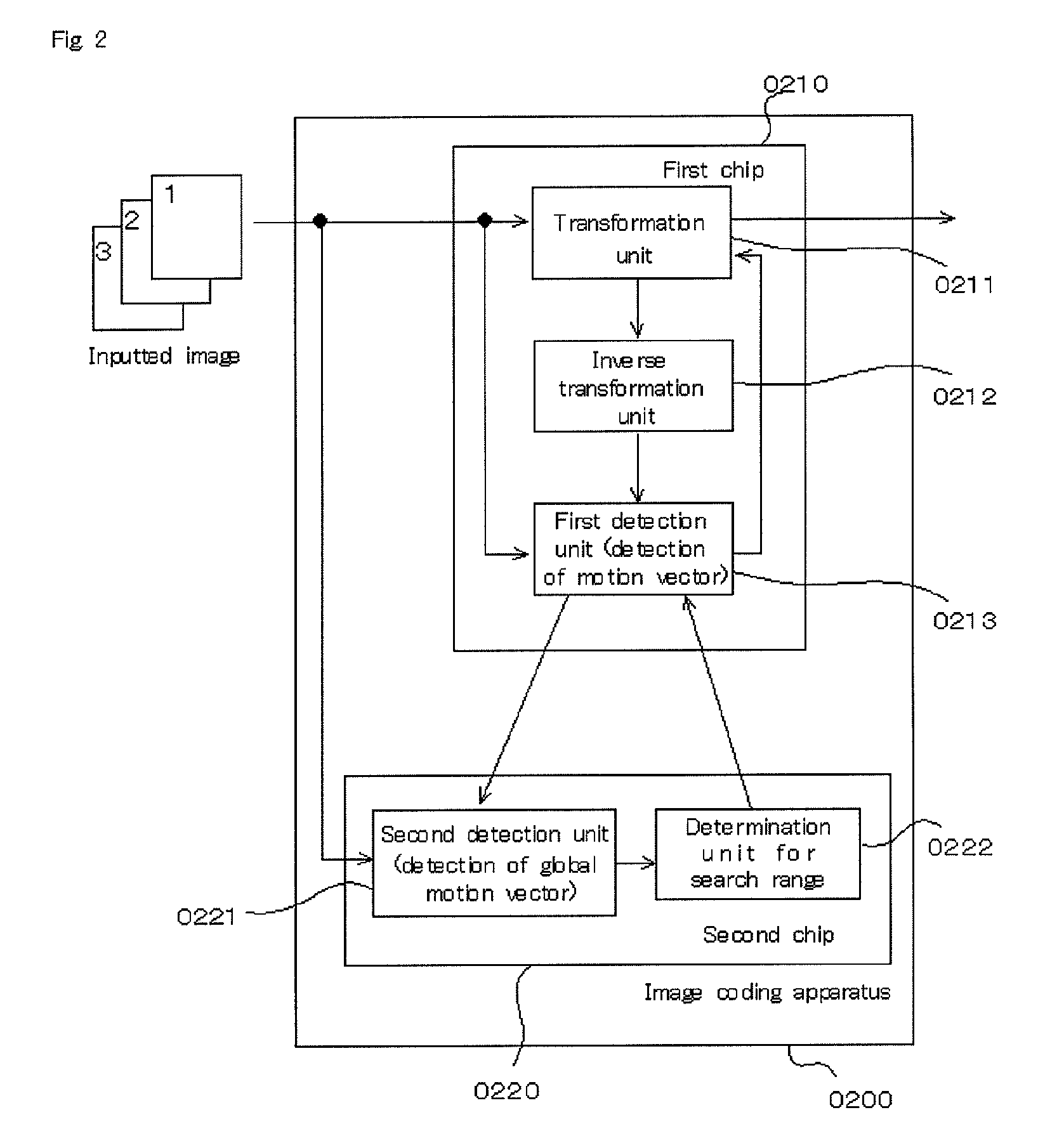
[0031]FIG. 2 is a functional block diagram of the image coding apparatus of the first embodiment. As shown in FIG. 2, an ‘image coding apparatus’ (0200) is an image coding apparatus for coding an inputted image by means of a motion vector, comprising a ‘first chip’ (0210), a ‘second chip’ (0220), which are separately arranged. The ‘first chip’ comprises a ‘transformation unit’ (0211), an ‘inverse transformation unit’ (0212), and a ‘first detection unit’ (0213). The ‘second chip’ comprises a ‘second detection unit’ (0221), and a ‘determination unit for search range’ (0222), and respective processings can be carried out independently. Note that the configuration of the present invention may be a configuration in which the first chip and the second ship are physically separated, or a configuration in which the one hardware chip is separately operated in a software.

[0032]Note that, the functional block of the apparatuses described hereinbelow can be impl...

second embodiment

Configuration of Second Embodiment

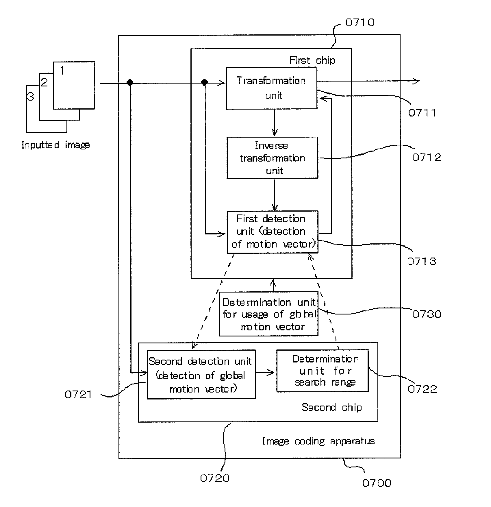
[0054]FIG. 7 is a functional block diagram of the image coding apparatus of the second embodiment. As shown in FIG. 7, an ‘image coding apparatus’ (0700) is based on the first embodiment, and comprises a ‘first chip’ (0710), a ‘second chip’ (0770), which are separately arranged. The ‘first chip’ comprises a ‘transformation unit’ (0711), an ‘inverse transformation unit’ (0712), and a ‘first detection unit’ (0713). The ‘second chip’ comprises a ‘second detection unit’ (0721), and a ‘determination unit for search range’ (0722), and respective processes can be carried out independently. Note that the above functional blocks have been described in the first embodiment, so that the descriptions thereof are omitted. In addition, the image coding apparatus of the second embodiment further comprises a ‘determination unit for utilization of global motion vector’ (0730).

[0055]The ‘determination unit for utilization of global motion vector’ (0730) has a functio...

third embodiment

Another Third Embodiment

[0070]Additionally, the image coding apparatus of the third embodiment may further comprise a ‘determination unit for size of global macro block’. The ‘determination unit for size of global macro block’ has a function of determining size of a global macro block based on the image size acquired by the acquisition unit for image size. This determination is carried out, for example, by a determination method by means of a correspondence table such as a table, in which in the case of image size ‘320×240’ pixels, a size of a global macro block is set to ‘32×24’ pixels, or a table, in which in the case of image size ‘1920×1080’ pixels, a size of a global macro block is set to ‘96×72’ pixels, or by a determination method for size of a macro block by means of a predetermined function f(x), in which image size is a parameter x. Therefore, the image coding apparatus of another third embodiment further has a function of determining the global macro block according to th...


PUM


Abstract

Since a global motion vector detector is disposed on the same chip as, for example, an image converter utilizing spatial correlations, a first problem is that an original frame is not completely reproduced in an image, since the frame to be referred to when detecting the global motion vector is an image obtained by inverse-converting a nonreversibly compression-converted image. A second problem is that, upon high-efficient image encoding, the detection process of the global motion vector is performed even when it is not necessary to detect the global motion vector. An image encoding apparatus is equipped with a mechanism for detecting a global motion vector. The mechanism is located outside an image converter that utilizes spatial correlations, such as high-frequency component removal by a DCT and round-down by a quantization, and variable encoding.

Description

BACKGROUND OF THE INVENTION[0001]1. Field of the Invention[0002]The present invention relates to an image coding apparatus utilizing global motion vector upon coding of image inputted by means of motion vector.[0003]2. Description of the Related Art[0004]Conventionally, in high-efficiency coding of image, the following three image transformations are mainly used for compressing amounts of moving image information, thereby carrying out coding. Therefore, the three image transformations are the first image transformation by means of correlation of image (spatial correlation), the second image transformation by means of correlation between times (time correlation), and the third image transformation by means of variable length coding. Specifically, in the second coding by means of time correlation, moving direction and moving distance of image between temporally-different frames (inputted images) are detected as ‘motion vector’ on a macro block basis, and a frame is expressed based on ...

Claims


Application Information

Patent Timeline
Patent Type & Authority Patents(United States)
IPC IPC(8): H04N7/12H04N11/02H04N11/04H04B14/04H03M7/36H04N19/105H04N19/134H04N19/139H04N19/436H04N19/50H04N19/527H04N19/57H04N19/625H04N19/91
CPCH04N19/52H04N19/172H04N19/51H04N19/57H04N19/136H04N19/527H04N19/523H04N19/103H04N19/43
Inventor NISHIDA, KAZUHITO
Owner SHARP KK
Learn More